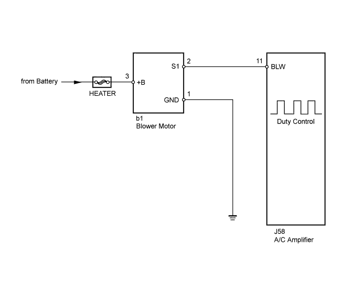
AIR CONDITIONING SYSTEM Blower Motor Circuit
DESCRIPTION
The blower motor is operated by signals from the A/C amplifier. Blower motor speed signals are transmitted in accordance with changes in the duty ratio.
WIRING DIAGRAM
INSPECTION PROCEDURE
PROCEDURE
-
PERFORM ACTIVE TEST USING INTELLIGENT TESTER
-
Connect the intelligent tester to the DLC3.
-
Turn the engine switch on (IG).
-
Turn the intelligent tester on.
-
Select the item below in the Active Test and then check that the relay operates.
Active Test / Air Conditioner Tester Display Test Part Control Range Diagnostic Note Blower Motor
(Blower Motor)
Blower motor Min.: 0, Max.: 31 - Result Result Proceed to OK A NG (blower motor does not operate) B NG (blower motor operates but does not change speed) C
B 
INSPECT FUSE (HEATER) Click here
C
CHECK HARNESS AND CONNECTOR (A/C AMPLIFIER - BODY GROUND) Click here
A 
PROCEED TO NEXT CIRCUIT INSPECTION SHOWN IN PROBLEM SYMPTOMS TABLE Click here
-
-
INSPECT FUSE (HEATER)
-
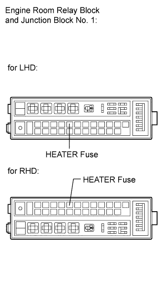
Remove the HEATER fuse from the engine room relay block and junction block No. 1.
-
Measure the resistance according to the value(s) in the table below.
Standard Resistance Tester Item Condition Specified Condition HEATER fuse Always Below 1 Ω
NG 
REPLACE FUSE (HEATER)
OK 
-
-
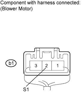
CHECK HARNESS AND CONNECTOR (BLOWER MOTOR - BODY GROUND)
-
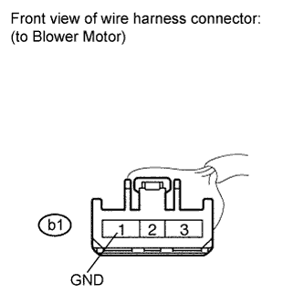
Disconnect the blower motor connector.
-
Measure the resistance according to the value(s) in the table below.
Standard Resistance Tester Connection Condition Specified Condition b1-1 (GND) - Body ground Always Below 1 Ω
NG
REPAIR OR REPLACE HARNESS OR CONNECTOR
OK
-
-
CHECK HARNESS AND CONNECTOR (BLOWER MOTOR - BATTERY)
-
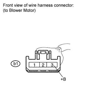
Measure the voltage according to the value(s) in the table below.
Standard Voltage Tester Connection Condition Specified Condition b1-3 (+B) - Body ground Always 11 to 14 V
NG
REPAIR OR REPLACE HARNESS OR CONNECTOR
OK
-
-
INSPECT BLOWER MOTOR
-
Reconnect the blower motor connector.
-
Measure the voltage according to the value(s) in the table below.
Standard Voltage Tester Connection Condition Specified Condition b1-2 (S1) - Body ground Always 4.5 to 5.5 V
NG
REPLACE BLOWER MOTOR Click here
OK
-
-
CHECK HARNESS AND CONNECTOR (A/C AMPLIFIER - BODY GROUND)
-
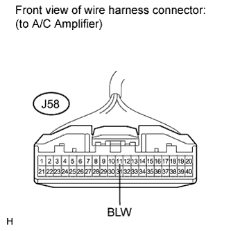
Disconnect the A/C amplifier connector.
-
Measure the voltage according to the value(s) in the table below.
Standard Voltage Tester Connection Condition Specified Condition J58-11 (BLW) - Body ground Always 4.5 to 5.5 V
NG
REPAIR OR REPLACE HARNESS OR CONNECTOR
OK
-
-
INSPECT AIR CONDITIONING AMPLIFIER
-
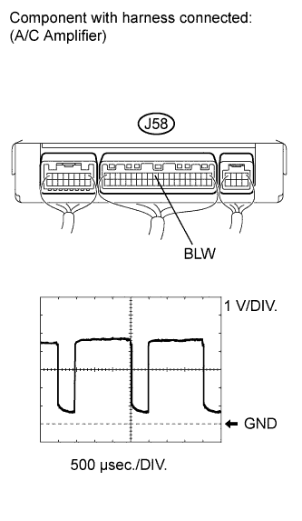
Remove the A/C amplifier.
-
Reconnect the A/C amplifier connector.
-
Turn the engine switch on (IG) .
-
Turn the blower switch on (LO).
-
Measure the waveform between terminal J58-11 (BLW) of the A/C amplifier and body ground.
OK Waveform is as shown in the illustration. Tech Tips
The waveform varies with the blower speed.
Item Content Tool setting 1 V/DIV., 500 μs/DIV. Vehicle condition Engine switch on (IG)
Blower switch ON (LO)
NG
REPLACE A/C AMPLIFIER Click here
OK
PROCEED TO NEXT CIRCUIT INSPECTION SHOWN IN PROBLEM SYMPTOMS TABLE Click here
-