AIR CONDITIONING SYSTEM DIAGNOSIS SYSTEM

-
DESCRIPTION
-
Air conditioning system data and Diagnostic Trouble Codes (DTCs) can be read through the Data Link Connector 3 (DLC3) of the vehicle. When the system seems to be malfunctioning, use the intelligent tester to check for malfunctions and perform troubleshooting.
-
-
CHECK DLC3
-
Check the DLC3 Click here.
-
-
LIST OF OPERATION METHODS
-
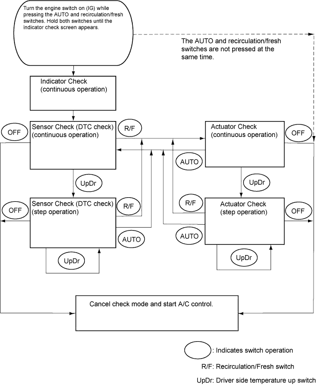
By operating each of the air conditioning control switches as shown in the diagram below, it is possible to enter diagnostic check mode.
-
-
INDICATOR CHECK
-
Turn the engine switch off.
-
Turn the engine switch on (ACC) and wait at least 5 seconds.
-
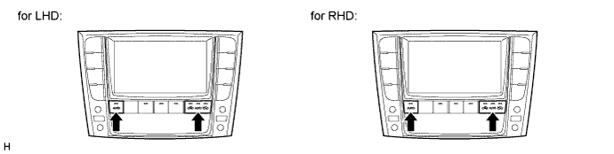
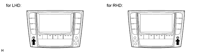
Turn the engine switch on (IG) while pressing the A/C control AUTO switch and recirculation/fresh switch simultaneously. Hold both switches until the indicator check screen appears.
-
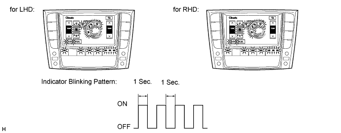
The indicator check is automatically performed when panel diagnosis is activated. Check that the indicators light up and go off at 1 second intervals 4 times in succession.
Tech Tips
-
The sensor check automatically starts when the indicator check is completed.
-
Press the OFF switch to cancel check mode.
-
-
-
SENSOR CHECK (DTC CHECK)
-
Start the engine and warm it up.
-
Perform the indicator check.
Tech Tips
After the indicator check is completed, the system enters DTC check mode automatically.
-
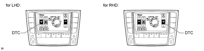
Read the DTC displayed on the panel.
Note
-
In sensor check mode, which is automatically entered after indicator check mode, troubleshooting may be partially performed. Be sure to perform the actuator check, and then the sensor check again.
-
If the check is performed in a dark place, DTC 21 or 24 may be displayed even though the system is normal.
Tech Tips
Refer to the DTC chart (Diagnostic Trouble Code chart) for details of the codes Click here.
-
When there are no problems, DTC 00 is output.
-
As an example, the illustration shows that DTC 12 is output.
-
-
If the steps are difficult to read because they change automatically, push the driver side TEMP up switch to display the steps one at a time so that they can be read easily. The items are displayed step by step each time the driver side TEMP up switch is pushed.
-
Push the OFF switch to finish panel diagnosis.
-
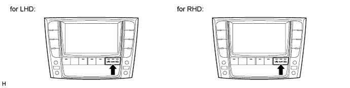
Push the recirculation/fresh switch to enter actuator check mode.
-
-
Clear the DTCs.
-
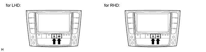
During the sensor check, press the front defroster switch and rear defroster switch at the same time.
-
-
-
ACTUATOR CHECK
-
Start the engine and warm it up.
-
Perform the indicator check.
-
Push the recirculation/fresh switch to perform the actuator check.
Tech Tips
Be sure to perform the actuator check after starting the engine.
-
As the actuator check is repeated from steps 1 to 10 at 1 second intervals, check the temperature and air flow visually and by hand.
Tech Tips
-
The display blinks at 1 second intervals in step operation.
-
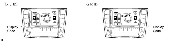
As an example, the illustration shows that display code 5 is output.
-
Push the OFF switch to finish panel diagnosis.
-
Push the AUTO switch to enter sensor check mode.
Step No. Display Code Condition Blower Level Air Mix Damper Airflow Vent Air Inlet Damper Cool Air By-pass Damper Compressor 1 0 0 0% open FACE FRESH -14% OFF 2 1 1 0% open FACE FRESH -14% OFF 3 2 17 0% open FACE RECIRCULATION / FRESH -14% ON 4 3 17 0% open FACE RECIRCULATION 113.50% ON 5 4 17 50% open B/L RECIRCULATION 113.50% ON 6 5 17 50% open B/L RECIRCULATION 113.50% ON 7 6 17 50% open FOOT FRESH 113.50% ON 8* 7 17 100% open FOOT-0 FRESH 113.50% ON 9 8 17 100% open F/D FRESH 113.50% ON 10 9 31 100% open DEF FRESH 113.50% ON Tech Tips
*: This only occurs for check mode. The air outlets remain the same but the air mix damper position will differ.
-
-
If the steps are difficult to read because they change automatically, push the driver side TEMP up switch to display the steps one at a time so that they can be read easily. The items are displayed step by step each time the driver side TEMP up switch is pushed.
Tech Tips
-
Push the OFF switch to finish panel diagnosis.
-
Push the recirculation/fresh switch to enter sensor check mode.
-
-