AIR CONDITIONING SYSTEM TERMINALS OF ECU

-
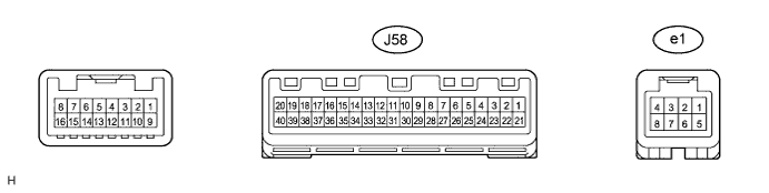
A/C AMPLIFIER
Tech Tips
Check from the rear of the connector while it is connected to the A/C amplifier.
Terminal No. (Symbol) Wiring Color Terminal Description Condition Specified Condition J58-1 (B) - J58-20 (GND) Y - W-B Power source (Back-up) Always 11 to 14 V J58-2 (MHTR) - J58-20 (GND) BR - W-B Mirror heater relay signal Engine switch on (IG), REAR DEF switch: OFF 11 to 14 V J58-2 (MHTR) - J58-20 (GND) BR - W-B Mirror heater relay signal Engine switch on (IG), REAR DEF switch: ON Below 1 V J58-3 (RDFG) - J58-20 (GND) B - W-B DEFOG relay signal Engine switch on (IG), FRONT DEF switch: OFF 11 to 14 V J58-3 (RDFG) - J58-20 (GND) B - W-B DEFOG relay signal Engine switch on (IG), FRONT DEF switch: ON Below 1 V J58-5 (SOL+) - J58-20 (GND) G - W-B A/C compressor operation signal Engine switch on (IG), A/C switch: ON Pulse generation
(See waveform 1)
J58-11 (BLW) - J58-20 (GND) BE - W-B Blower motor speed control signal Engine switch on (IG), Blower switch: ON Pulse generation
(See waveform 2)
J58-13 (PRE) - J58-38 (SG-2) V - P A/C pressure sensor signal Engine running, A/C switch: ON
Refrigerant pressure: Abnormal pressure (more than 3030 kPa (31.0 kgf/cm2, 440 psi))
4.77 V or higher J58-13 (PRE) - J58-38 (SG-2) V - P A/C pressure sensor signal Engine running, A/C switch: ON
Refrigerant pressure: Abnormal pressure (less than 180 kPa (1.9 kgf/cm2, 27 psi))
Below 0.767 V J58-13 (PRE) - J58-38 (SG-2) V - P A/C pressure sensor signal Engine running, A/C switch: ON
Refrigerant pressure: Normal pressure (less than 3030 kPa (31.0 kgf/cm2, 440 psi) and more than 180 kPa (1.9 kgf/cm2, 27 psi))
0.767 to 4.77 V J58-14 (TSP) - J58-20 (GND) P - W-B Passenger side solar sensor signal Engine switch on (IG), Solar sensor subjected to electric light 0.8 to 4.3 V J58-14 (TSP) - J58-20 (GND) P - W-B Passenger side solar sensor signal Engine switch on (IG), Solar sensor is covered with a cloth Below 0.8 V J58-16 (TR) - J58-19 (SG-1) G - L Room temperature sensor signal Engine switch on (IG), Cabin temperature: 25°C (77°F) 1.9 to 2.1 V J58-16 (TR) - J58-19 (SG-1) G - L Room temperature sensor signal Engine switch on (IG), Cabin temperature: 40°C (104°F) 1.3 to 1.5 V J58-19 (SG-1) - Body ground L - Body ground Ground for room temperature sensor Always Below 1 V J58-20 (GND) - Body ground W-B - Body ground Ground for main power supply Always Below 1 V J58-21 (IG+) - J58-20 (GND) B - W-B Power source (IG) Engine switch on (IG) 11 to 14 V J58-21 (IG+) - J58-20 (GND) B - W-B Power source (IG) Engine switch off Below 1 V J58-26 (S5-2) - J58-38 (SG-2) W - P Power supply for A/C pressure sensor Engine switch on (IG) 4.75 to 5.25 V J58-26 (S5-2) - J58-38 (SG-2) W - P Power supply for A/C pressure sensor Engine switch off Below 1 V J58-30 (MPX+) - J58-20 (GND) BR - W-B Multiplex communication system Engine idling after engine warmed up Pulse generation J58-31 (MPX-) - J58-20 (GND) BR - W-B Multiplex communication system Engine idling after engine warmed up Pulse generation J58-33 (DGS1) - J58-39 (SG-6) R - Y Smog ventilation sensor signal (NOx) 30 seconds after engine switch turned on (IG) and sensor exposed to exhaust gas 1.0 to 4.5 V J58-34 (DGS) - J58-39 (SG-6) BR - Y Smog ventilation sensor signal (HC, CO) 30 seconds after engine switch turned on (IG) and sensor exposed to exhaust gas 1.0 to 4.5 V J58-35 (TSD) - J58-20 (GND) LG - W-B Driver side solar sensor signal Engine switch on (IG), Solar sensor subjected to electric light 0.8 to 4.3 V J58-35 (TSD) - J58-20 (GND) LG - W-B Driver side solar sensor signal Engine switch on (IG), Solar sensor is covered with a cloth Below 0.8 V J58-36 (TAM) - J58-37 (SG) L - LG Ambient temperature sensor signal Engine switch on (IG), Ambient temperature: 25°C (77°F) 1.35 to 1.75 V J58-36 (TAM) - J58-37 (SG) L - LG Ambient temperature sensor signal Engine switch on (IG), Ambient temperature: 40°C (104°F) 0.9 to 1.2 V J58-37 (SG) - Body ground LG - Body ground Ground for ambient temperature sensor Always Below 1 V J58-38 (SG-2) - Body ground P - Body ground Ground for A/C pressure sensor Always Below 1 V J58-39 (SG-6) - Body ground Y - Body ground Ground for smog ventilation sensor Always Below 1 V e1- 2 (BUS G) - Body ground - Ground for BUS IC Always Below 1 V e1- 3 (BUS) - e1-2 (BUS G) - BUS IC control signal Engine switch off → on (IG) Pulse generation e1-4 (B BUS) - e1-2 (BUS G) - Power supply for BUS IC Always 11 to 14 V e1-4 (B BUS) - e1-2 (BUS G) - Power supply for BUS IC Engine switch off Below 1 V e1-5 (SG) - Body ground - Ground for evaporator temperature sensor signal Always Below 1 V e1-6 (TE) - e1-5 (SG) - Evaporator temperature sensor signal Engine switch on (IG), Evaporator temperature: 0°C (32°F) 1.7 to 2.1 V e1-6 (TE) - e1-5 (SG) - Evaporator temperature sensor signal Engine switch on (IG), Evaporator temperature: 15°C (59°F) 0.9 to 1.3 V
-
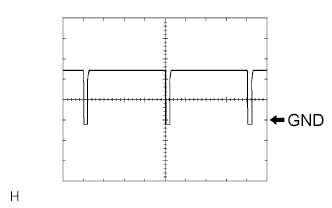
Waveform 1
Item Content Terminal No.
(Symbol)
J58-5 (SOL+) - J58-20 (GND) Tool Setting 5 V/DIV.,
500 μs/DIV.
Vehicle Condition Engine switch on (IG)
A/C switch: ON
-
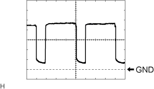
Waveform 2
Item Content Terminal No.
(Symbol)
J58-11 (BLW) - J58-20 (GND) Tool Setting 1 V/DIV.,
500 μs/DIV.
Vehicle Condition Engine switch on (IG)
Blower switch: ON
-
-
INTEGRATION CONTROL AND PANEL ASSEMBLY (w/o Navigation System)

Terminal No. (Symbol) Wiring Color Terminal Description Condition Specified Condition J54-4 (IG+) - J54-8 (E) B - W-B Power source (IG) Engine switch on (IG) 11 to 14 V J54-4 (IG+) - J54-8 (E) B - W-B Power source (IG) Engine switch off Below 1 V J54-5 (ACC) - J54-8 (E) BE - W-B Power source (ACC) Engine switch on (ACC) 11 to 14 V J54-5 (ACC) - J54-8 (E) BE - W-B Power source (ACC) Engine switch off Below 1 V J54-8 (E) - Body ground W-B - Body ground Ground for integration control and panel assembly Always Below 1 V J54-14 (B) - J54-8 (E) LG - W-B Power source (Back-up) Always 11 to 14 V -
RADIO RECEIVER ASSEMBLY (w/o Navigation System) Click here
-
MULTI-DISPLAY ASSEMBLY (w/ Navigation System) Click here
-
MULTI-MEDIA MODULE RECEIVER ASSEMBLY (w/ Navigation System) Click here