AIR CONDITIONING SYSTEM SYSTEM DESCRIPTION

-
GENERAL
The air conditioning system has the following controls:
Control Outline Neural Network Control This control is capable of effecting complex control by artificially simulating the information processing method of the nervous system of living organisms in order to establish a complex input/output relationship that is similar to a human brain. Automatic Recirculation Control Automatically changes the air inlet mode to fresh air or recirculation air mode according to the level of harmful elements in the outside air, cabin temperature, and outside temperature. Pollen Removal Mode Control Activated by operation of the pollen removal mode switch this control switches the air vent to FACE mode and sends air which has passed through the clean air filter to the area around the upper part of the bodies of the driver and front passenger. Outlet Air Temp. Control Based on the temperature set at the temperature control switch, the neural network control calculates the outlet air temperature based on the input signals from various sensors. This air is filtered by the clean air filter in order to remove pollen. The temperature setting for the driver and front passenger is controlled independently in order to provide a separate vehicle interior temperature for the right and left side of the vehicle. Blower Control Controls the blower motor in accordance with the airflow volume that has been calculated by the neural network control based on the input signals from various sensors. Air Outlet Control Automatically switches the air outlets in accordance with the outlet mode that has been calculated by the neural network control based on the input signals from various sensors. In accordance with the engine coolant temperature, outside air temperature, amount of sunlight, required blower, outlet temperature, and vehicle speed conditions, this control automatically switches the blower outlet to foot/defroster mode to prevent the windows from becoming fogged when the outside air temperature is low. Air Inlet Control Automatically controls the air inlet control damper to achieve the calculated outlet air temperature that is required. Drives the servo motor (for air inlet) according to the operation of the air inlet control switch and moves the dampers to the FRESH or RECIRC position. Compressor Control This control turns off the magnetic clutch of the A/C compressor when the blower motor is turned off when the engine coolant temperature is below a predetermined value, an abnormal refrigerant pressure has been detected, or the discharge temperature of the evaporator is below a predetermined value (evaporator too cold). The A/C amplifier turns the compressor off if the engine coolant temperature becomes abnormally hot (115 °C (239 °F) or above) when driving under a high load. Rear Window Defogger Control Switches the rear defogger and outside rear view mirror heaters on for 15 minutes when the rear defogger button is and switches them off if the button is pressed while they are operating. Outside Temperature Indication Control Based on the signals from the ambient temperature sensor, this control calculates the outside temperature, which is then corrected in the A/C amplifier and shown in the multi-display. Self-Diagnosis A DTC (Diagnostic Trouble Code) is stored in the memory when the A/C amplifier detects a problem with the air conditioning system. -
NEURAL NETWORK CONTROL
-
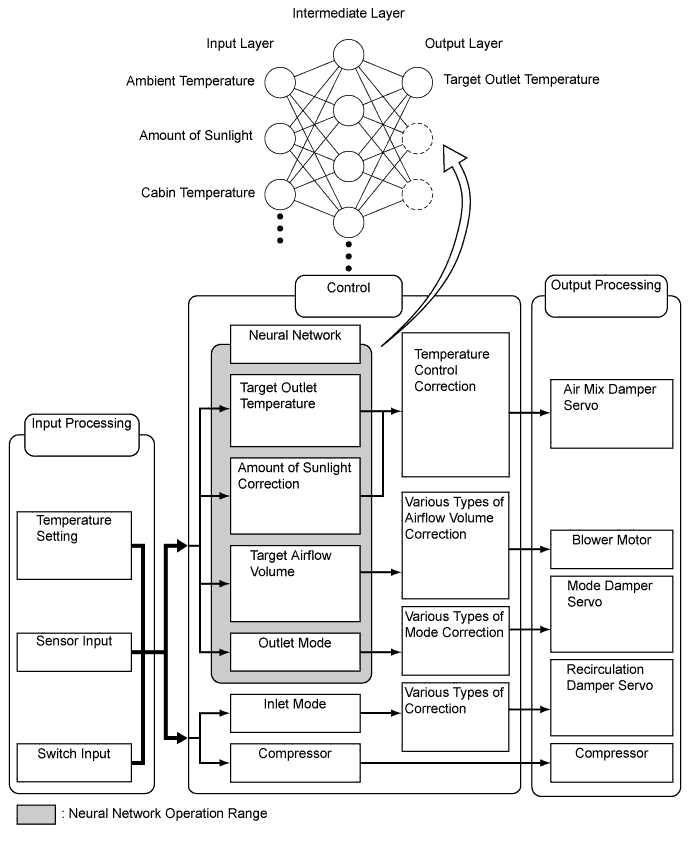
In previous automatic air conditioning systems, the A/C amplifier determined the required outlet air temperature and blower air volume in accordance with the calculation formula that has been obtained based on information received from the sensors.
However, because the senses of a person are rather complex, a given temperature is sensed differently, depending on the environment in which the person is situated. For example, a given amount of solar radiation can feel comfortably warm in a cold climate, or extremely uncomfortable in a hot climate. Therefore, as a technique for effecting a higher level of control, a neural network has been adopted in the automatic air conditioning system. With this technique, the data that has been collected under varying environmental conditions is stored in the A/C amplifier. The A/C amplifier can then effect control to provide enhanced air conditioning comfort.
-
The neural network control consists of neurons in the input layer, intermediate layer, and output layer. The input layer neurons process the input data of the outside temperature, the amount of sunlight, and the room temperature based on the outputs of the switches and sensors, and output them to the intermediate layer neurons. Based on this data, the intermediate layer neurons adjust the strength of the links among the neurons. The sum of these is then calculated by the output layer neurons in the form of the required outlet temperature, solar correction, target airflow volume, and outlet mode control volume. Accordingly, the A/C amplifier controls the servo motors and blower motor in accordance with the control volumes that have been calculated by the neural network control.
-
-
AUTOMATIC RECIRCULATION CONTROL
-
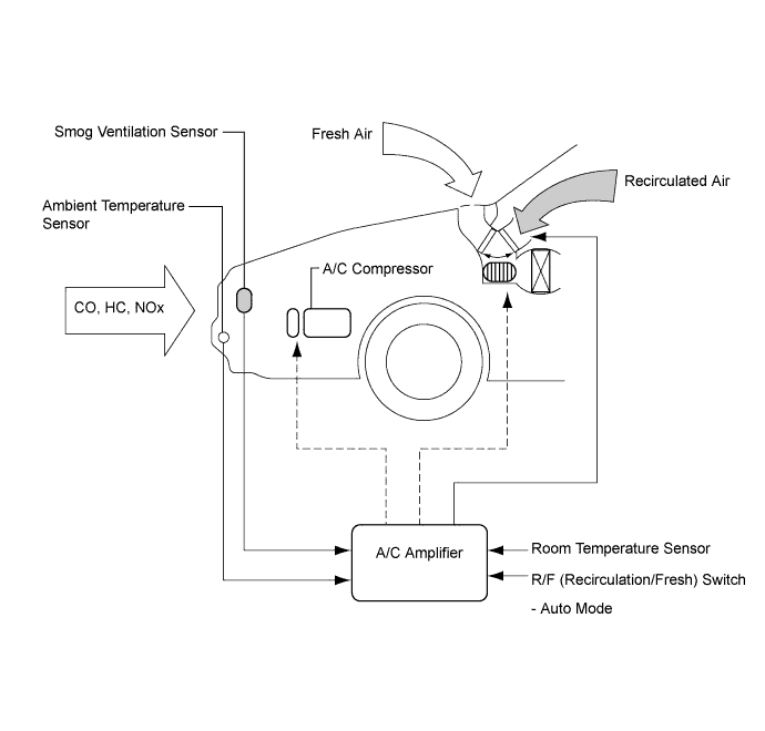
When the automatic recirculation control is operating, the A/C amplifier automatically changes the air inlet mode to fresh air or recirculation air mode based on signals from the smog ventilation sensor, ambient temperature, and room temperature sensors when AUTO air inlet mode is selected.
-
The A/C amplifier detects harmful elements (CO, HC, and NOx) based on smog ventilation sensor signals and automatically switches the air inlet mode to recirculation air mode to prevent such harmful elements from entering the cabin.
-
The A/C amplifier detects cabin temperature based on the room temperature sensor signal and automatically switches the air inlet mode to recirculation air mode to prevent the cabin temperature from becoming too high.
-
The A/C amplifier detects the outside temperature based on the ambient temperature sensor signal and automatically switches the air inlet mode to fresh air mode to prevent the windshield from fogging up.
-
-
-
POLLEN REMOVAL MODE CONTROL
-
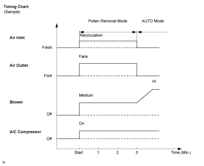
When the pollen removal mode switch is pressed, the pollen removal mode control is activated. Then, the air vent is switched to face mode and recirculated pollen free air flows in the area around the upper part of the bodies of the driver and front passenger.
-
When the pollen removal mode switch signal is input to the A/C amplifier, the A/C amplifier controls the A/C compressor, air inlet control servo motor, air outlet control servo motor and blower motor as shown in the timing chart.
-
This control usually operates for approximately 3 minutes. However, when the outside temperature is low, it will operate for approximately 1 minute.
-
After this control stops operating, the A/C amplifier controls the air conditioning system using AUTO mode.
-
-
-
MODE POSITION AND DAMPER OPERATION
-
Mode Position and Damper Operation
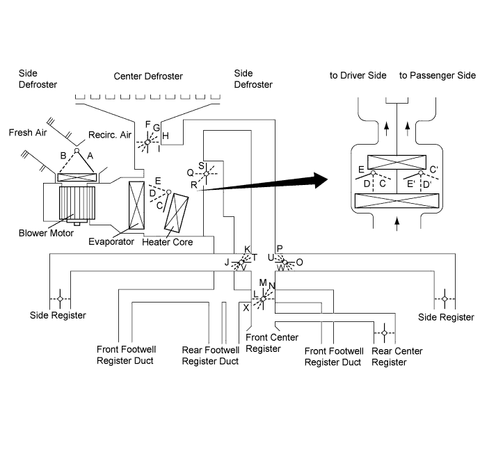
Functions of Main Dampers Control Damper Operation Position Damper Position Operation Air Inlet Control Damper FRESH A Allows fresh air to enter. RECIRCULATION B Causes internal air to recirculate. Air Mix Control Damper MAX COLD to MAX HOT Temperature Setting C - D - E
(C' - D' - E')
Varies the mixture ratio of the hot air and the cold air in order to regulate the temperature continuously between hot and cold. Air Outlet Control Damper DEF

F, V, L, W, S Defrosts the windshield through the center defroster, side defrosters. FOOT/DEF

G, K, X, P, Q Defrosts the windshield through the center defroster, side defrosters, side registers, and rear center register, while air is also blown out from the front center register, front footwell register ducts and rear footwell register ducts. FOOT

H, K, X, P, Q Air blows out of the front and rear footwell register ducts and side registers. In addition, a small amount of air will blow out from the front center register, center defroster and side defrosters. BI-LEVEL

I, T, N, U, R Air blows out of the front and rear center registers, side registers and front and rear footwell register ducts. FACE

I, J, M, O, S Air blows out of the front and rear center registers and side registers.
-
-
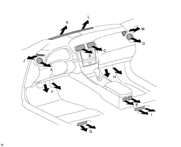
AIR OUTLETS AND AIRFLOW VOLUME
-
Air Outlets and Airflow Volume
-
for LHD:
-
for RHD:
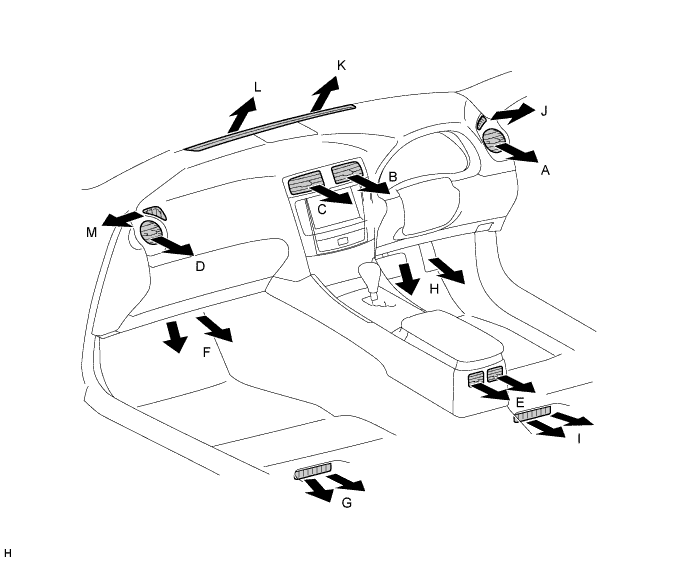
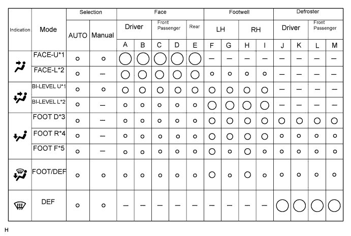
The size of the circle ○ indicates the proportion of airflow volume.
*1: Greater airflow volume at the upper area
*2: Greater airflow volume at the lower area
*3: Greater airflow volume at the defroster
*4: Greater airflow volume at the rear
*5: Greater airflow volume at the front
-
-
-
EVAPORATOR TEMPERATURE SENSOR
The evaporator temperature sensor detects the temperature of the cool air immediately through the evaporator in the form of resistance changes, and outputs it to the A/C amplifier.
-
BLOWER MOTOR
The blower motor has a built-in blower controller, and is controlled using duty control performed by the A/C amplifier.
-
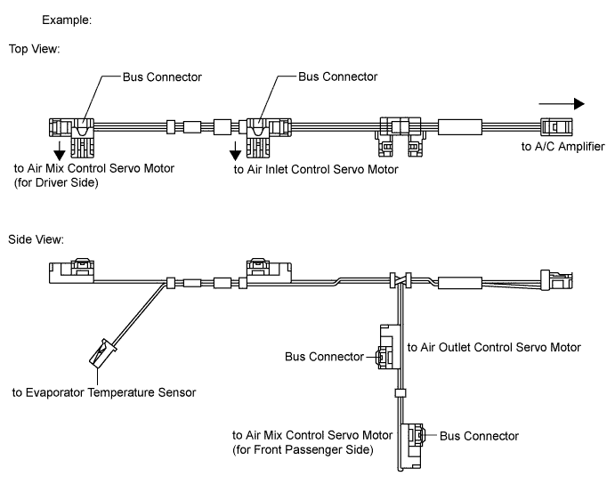
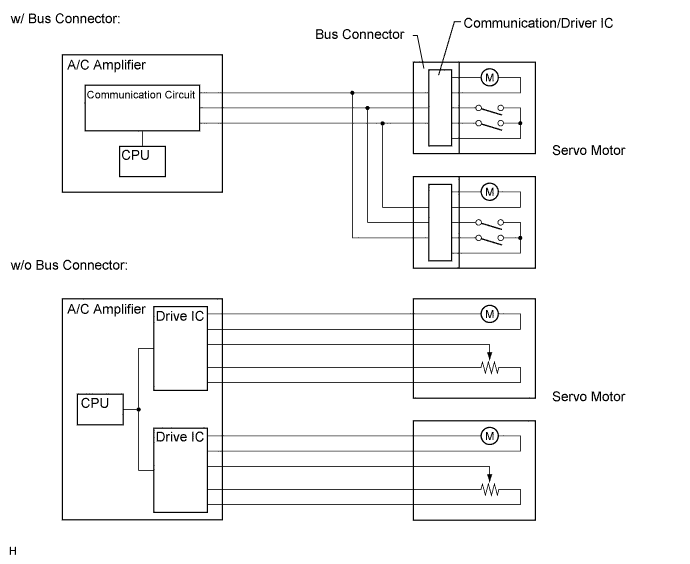
BUS CONNECTOR
-
Bus connectors are used in the wire harness that connects the servo motors to the A/C amplifier.
-
Each bus connector has a built-in communication/driver IC which communicates with the servo motor connector, actuates the servo motor, and has a position detection function. This enables bus communication for the servo motor wire harness, for a more lightweight construction and a reduced number of wires.
-
-
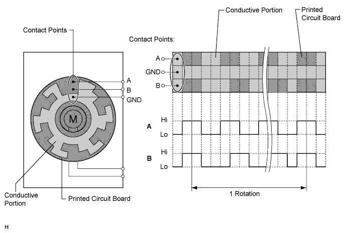
SERVO MOTOR
-
A pulse pattern type servo motor consists of a printed circuit board and a servo motor. The printed circuit board has three contact points, and can transmit two ON-OFF signals to the A/C amplifier based on the difference of the pulse phases. The bus connector can detect the damper position and movement direction with these signals.
-
-
ROOM TEMPERATURE SENSOR
The room temperature sensor detects the cabin temperature based on changes in the resistance of its built-in thermistor and sends a signal to the A/C amplifier.
-
AMBIENT TEMPERATURE SENSOR
The ambient temperature sensor detects the outside temperature based on changes in the resistance of its built-in thermistor and sends a signal to the A/C amplifier.
-
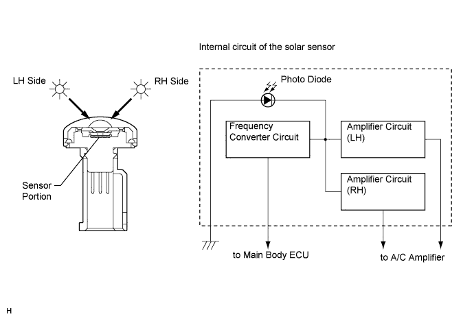
SOLAR SENSOR
-
The solar sensor consists of a photo diode, two amplifier circuits for the solar sensor, and frequency converter circuit for the light control sensor.
-
The solar sensor detects (in the form of changes in the current that flows through the built-in photo diode) the changes in the amount of sunlight from the LH and RH sides (2 directions) and outputs these sunlight strength signals to the A/C amplifier.
-
-
A/C PRESSURE SENSOR
The A/C pressure sensor detects the refrigerant pressure and outputs it to the A/C amplifier in the form of voltage changes.
-
SMOG VENTILATION SENSOR
-
The smog ventilation sensor detects harmful elements such as CO, HC, and NOx present in the air outside of the vehicle and sends a signal to the A/C amplifier.
-
The sensitivity of the smog ventilation sensor can be adjusted. Adjustment can be done using the heater control panel or multi-display.
-