REAR SEAT OUTER BELT ASSEMBLY INSTALLATION

-
INSTALL REAR SEAT 3 POINT TYPE BELT ASSEMBLY
-
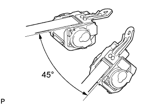
Check the degree of the tilt when the ELR begins to lock.
-
Check that the belt does not lock at less than 15 degrees of tilt in any direction but locks at over 45 degrees of tilt while gently pulling the belt.
Note
Do not disassemble the retractor.
-
-
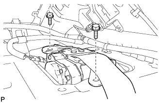
Temporarily install the rear seat 3 point type belt assembly with the 2 bolts.
-
Fully tighten the rear side bolt first, then the front side bolt to install the rear seat 3 point type belt assembly.
- Torque:
- For front bolt
- 7.5 N*m { 77 kgf*cm, 66 in.*lbf }
- For rear bolt
- 42 N*m { 428 kgf*cm, 31 ft.*lbf }
-
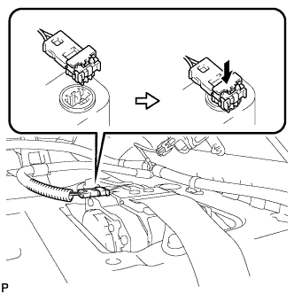
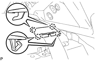
Connect the pretensioner connector and lock the locking button as shown in the illustration.
-
-
INSTALL PACKAGE TRAY TRIM PANEL ASSEMBLY
-
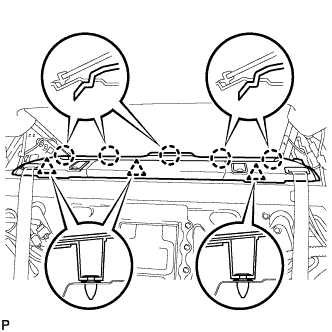
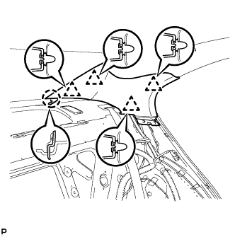
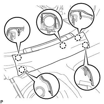
Pass the 2 rear seat belt floor anchors through the package tray trim panel assembly.
-
Engage the 3 clips and 5 claws to install the package tray trim panel assembly.
-
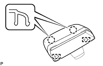
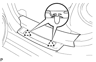
Engage the 4 claws to install the rear seat shoulder belt cover LH.
Tech Tips
Use the same procedures for the RH side and the LH side.
-
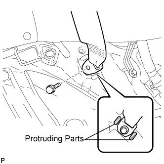
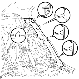
Install the floor end of the rear seat 3 point type belt assembly LH with the bolt.
- Torque:
- 42 N*m { 428 kgf*cm, 31 ft.*lbf }
Note
Do not allow the anchor part of the rear seat 3 point type belt assembly LH to overlap protruding parts of the floor panel.
Tech Tips
Use the same procedure for the RH side and the LH side.
-
Check if the ELR locks.
Note
The check should be performed with the outer belt assembly installed.
-
With the belt assembly installed, check that the belt locks when it is pulled out quickly.
-
-
-
INSTALL CENTER STOP LIGHT SET
-
Connect the connector.
-
Engage the 2 guides.
-
Engage the 2 claws and install the center stop light set.
-
-
INSTALL ROOF SIDE INNER GARNISH LH
-
Engage the claw and 4 clips, and install the roof side garnish inner LH.
-
-
INSTALL ROOF SIDE INNER GARNISH RH
Tech Tips
Use the same procedure for the RH side and the LH side.
-
INSTALL REAR SEAT SIDE GARNISH LH
-
Engage the 5 claws and install the rear seat side garnish LH.
-
-
INSTALL REAR SEAT SIDE GARNISH RH
Tech Tips
Use the same procedure for the RH side and the LH side.
-
INSTALL REAR DOOR SCUFF PLATE LH
-
Engage the 2 clips.
-
Engage the 5 claws and install the rear door scuff plate LH.
-
-
INSTALL REAR DOOR SCUFF PLATE RH
Tech Tips
Use the same procedure for the RH side and the LH side.
-
INSTALL REAR SEATBACK ASSEMBLY
-
Place the seatback in the cabin.
Note
Be careful not to damage the vehicle body.
-
Engage the 3 hooks.
-
Install the rear seatback assembly with the 4 bolts.
- Torque:
- 18 N*m { 184 kgf*cm, 13 ft.*lbf }
-
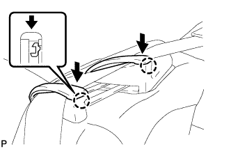
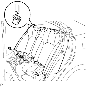
Pass the seat belt through the rear seat shoulder belt guide RH.
-
Engage the 2 claws and close the 2 caps of the rear seat shoulder belt guide RH.
-
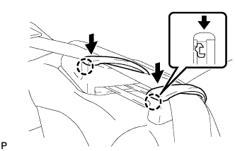
Pass the seat belt through the rear seat shoulder belt guide LH.
-
Engage the 2 claws and close the 2 caps of the rear seat shoulder belt guide LH.
-
-
INSTALL REAR SEAT CUSHION ASSEMBLY
-
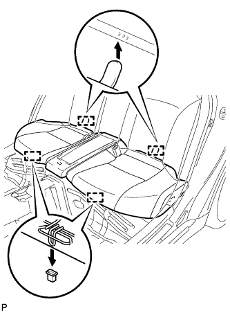
Engage the 2 rear hooks of the seat cushion to the child restraint seat anchor bracket.
-
Engage the 2 front hooks of the seat cushion to the vehicle body.
-
Confirm that the seat cushion is firmly installed.
Note
When installing the seat cushion, make sure the seat belt buckle is not under the seat cushion.
-
-
INSTALL REAR SEAT HEADREST ASSEMBLY LH
-
INSTALL REAR SEAT HEADREST ASSEMBLY RH
-
CONNECT CABLE TO NEGATIVE BATTERY TERMINAL
Note
Some systems need to be initialized after the cable is reconnected Click here.
-
INSPECT SRS WARNING LIGHT
Inspect the SRS warning light Click here.