FRONT POWER SEAT CONTROL SYSTEM TERMINALS OF ECU

-
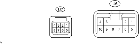
INSPECT FRONT POWER SEAT SWITCH LH (POSITION CONTROL ECU)
-
Disconnect the U7 and U6 ECU connectors.
-
Measure the voltage and resistance according to the value(s) in the table below.
Tester Connection Wiring Color Terminal Description Condition Specified Condition U7-4 (IG) - U6-1 (GND) Y - W-B Engine switch signal Engine switch off Below 1 V U7-4 (IG) - U6-1 (GND) Y - W-B Engine switch signal Engine switch on (IG) 11 to 14 V U6-5 (+B) - U6-1 (GND) L - W-B Power source Always 11 to 14 V U7-8 (SYSB) - U6-1 (GND) LG - W-B System power source Always 11 to 14 V U6-1 (GND) - Body ground W-B - Body ground Ground Always Below 1 Ω If the result is not as specified, there may be a malfunction on the wire harness side.
-
Reconnect the U7 and U6 ECU connectors.
-
Measure the voltage according to the value(s) in the table below.
Tester Connection Wiring Color Terminal Description Condition Specified Condition U6-2 (SLD+) - U6-1 (GND) B - W-B Sliding motor signal (forward) Slide switch OFF Below 1 V U6-2 (SLD+) - U6-1 (GND) B - W-B Sliding motor signal (forward) Slide switch FRONT ON 11 to 14 V U6-3 (SLD-) - U6-1 (GND) G - W-B Sliding motor signal (rearward) Slide switch OFF Below 1 V U6-3 (SLD-) - U6-1 (GND) G - W-B Sliding motor signal (rearward) Slide switch REAR ON 11 to 14 V U6-6 (FRV+) - U6-1 (GND) W - W-B Front vertical motor signal (upward) Front vertical switch OFF Below 1 V U6-6 (FRV+) - U6-1 (GND) W - W-B Front vertical motor signal (upward) Front vertical switch UP ON 11 to 14 V U6-4 (FRV-) - U6-1 (GND) R - W-B Front vertical motor signal (downward) Front vertical switch OFF Below 1 V U6-4 (FRV-) - U6-1 (GND) R - W-B Front vertical motor signal (downward) Front vertical switch DOWN ON 11 to 14 V U6-7 (LFT+) - U6-1 (GND) Y - W-B Lifter motor signal (upward) Lifter switch OFF Below 1 V U6-7 (LFT+) - U6-1 (GND) Y - W-B Lifter motor signal (upward) Lifter switch UP ON 11 to 14 V U6-9 (LFT-) - U6-1 (GND) LG - W-B Lifter motor signal (downward) Lifter switch OFF Below 1 V U6-9 (LFT-) - U6-1 (GND) LG - W-B Lifter motor signal (downward) Lifter switch DOWN ON 11 to 14 V U6-8 (RCL+) - U6-1 (GND) BR - W-B Reclining motor signal (forward) Reclining switch OFF Below 1 V U6-8 (RCL+) - U6-1 (GND) BR - W-B Reclining motor signal (forward) Reclining switch FRONT ON 11 to 14 V U6-10 (RCL-) - U6-1 (GND) GR - W-B Reclining motor signal (rearward) Reclining switch OFF Below 1 V U6-10 (RCL-) - U6-1 (GND) GR - W-B Reclining motor signal (rearward) Reclining switch REAR ON 11 to 14 V If the result is not as specified, the front power seat switch LH (position control ECU) may have a malfunction.
-
-
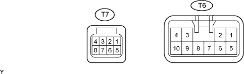
INSPECT FRONT POWER SEAT SWITCH RH (POSITION CONTROL ECU)
-
Disconnect the T6 and T7 ECU connectors.
-
Measure the voltage and resistance according to the value(s) in the table below.
Tester Connection Wiring Color Terminal Description Condition Specified Condition T7-4 (IG) - T6-1 (GND) B - W-B Engine switch signal Engine switch off Below 1 V T7-4 (IG) - T6-1 (GND) B - W-B Engine switch signal Engine switch on (IG) 11 to 14 V T6-5 (+B) - T6-1 (GND) L - W-B Power source Always 11 to 14 V T7-8 (SYSB) - T6-1 (GND) P - W-B System power source Always 11 to 14 V T6-1 (GND) - Body ground W-B - Body ground Ground Always Below 1 Ω If the result is not as specified, there may be a malfunction on the wire harness side.
-
Reconnect the T6 and T7 ECU connectors.
-
Measure the voltage according to the value(s) in the table below.
Tester Connection Wiring Color Terminal Description Condition Specified Condition T6-2 (SLD+) - T6-1 (GND) B - W-B Sliding motor signal (forward) Slide switch OFF Below 1 V T6-2 (SLD+) - T6-1 (GND) B - W-B Sliding motor signal (forward) Slide switch FRONT ON 11 to 14 V T6-3 (SLD-) - T6-1 (GND) G - W-B Sliding motor signal (rearward) Slide switch OFF Below 1 V T6-3 (SLD-) - T6-1 (GND) G - W-B Sliding motor signal (rearward) Slide switch REAR ON 11 to 14 V T6-6 (FRV+) - T6-1 (GND) W - W-B Front vertical motor signal (upward) Front vertical switch OFF Below 1 V T6-6 (FRV+) - T6-1 (GND) W - W-B Front vertical motor signal (upward) Front vertical switch UP ON 11 to 14 V T6-4 (FRV-) - T6-1 (GND) R - W-B Front vertical motor signal (downward) Front vertical switch OFF Below 1 V T6-4 (FRV-) - T6-1 (GND) R - W-B Front vertical motor signal (downward) Front vertical switch DOWN ON 11 to 14 V T6-7 (LFT+) - T6-1 (GND) Y - W-B Lifter motor signal (upward) Lifter switch OFF Below 1 V T6-7 (LFT+) - T6-1 (GND) Y - W-B Lifter motor signal (upward) Lifter switch UP ON 11 to 14 V T6-9 (LFT-) - T6-1 (GND) LG - W-B Lifter motor signal (downward) Lifter switch OFF Below 1 V T6-9 (LFT-) - T6-1 (GND) LG - W-B Lifter motor signal (downward) Lifter switch DOWN ON 11 to 14 V T6-8 (RCL+) - T6-1 (GND) BR - W-B Reclining motor signal (forward) Reclining switch OFF Below 1 V T6-8 (RCL+) - T6-1 (GND) BR - W-B Reclining motor signal (forward) Reclining switch FRONT ON 11 to 14 V T6-10 (RCL-) - T6-1 (GND) GR - W-B Reclining motor signal (rearward) Reclining switch OFF Below 1 V T6-10 (RCL-) - T6-1 (GND) GR - W-B Reclining motor signal (rearward) Reclining switch REAR ON 11 to 14 V If the result is not as specified, the front power seat switch RH (position control ECU) may have a malfunction.
-
-
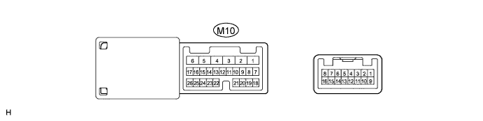
CHECK OUTER MIRROR CONTROL ECU LH
-
Disconnect the M10 ECU connector.
-
Measure the voltage and resistance according to the value(s) in the table below.
Tester Connection Wiring Color Terminal Description Condition Specified Condition M10-1 (GND) - Body ground W-B - Body ground Ground Always Below 1 Ω M10-4 (CPUB) - M10-1 (GND) G - W-B Battery (ECU power source) Always 11 to 14 V M10-3 (SIG) - M10-1 (GND) B - W-B Engine switch (IG) power supply Engine switch off Below 1 V M10-3 (SIG) - M10-1 (GND) B - W-B Engine switch (IG) power supply Engine switch on (IG) 11 to 14 V M10-6 (BDR) - M10-1 (GND) L - W-B Battery (ECU power source) Always 11 to 14 V If the result is not as specified, there may be a malfunction on the wire harness side.
-
Reconnect the M10 ECU connector.
-
Measure the voltage and resistance according to the value(s) in the table below.
Tester Connection Wiring Color Terminal Description Condition Specified Condition M10-26 (MSWE) - M10-1 (GND) O - W-B Ground for seat memory switch Always Below 1 Ω M10-25 (MM) - M10-26 (MSWE) W - O SET switch signal SET switch OFF 11 to 14 V M10-25 (MM) - M10-26 (MSWE) W - O SET switch signal SET switch ON Below 1 V M10-22 (M1) - M10-26 (MSWE) LG - O M1 switch signal M1 switch OFF 11 to 14 V M10-22 (M1) - M10-26 (MSWE) LG - O M1 switch signal M1 switch ON Below 1 V M10-23 (M2) - M10-26 (MSWE) R - O M2 switch signal M2 switch OFF 11 to 14 V M10-23 (M2) - M10-26 (MSWE) R - O M2 switch signal M2 switch ON Below 1 V M10-24 (M3) - M10-26 (MSWE) Y - O M3 switch signal M3 switch OFF 11 to 14 V M10-24 (M3) - M10-26 (MSWE) Y - O M3 switch signal M3 switch ON Below 1 V If the result is not as specified, the outer mirror control ECU LH may have a malfunction.
-
-
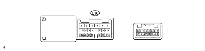
CHECK OUTER MIRROR CONTROL ECU RH
-
Disconnect the L10 ECU connector.
-
Measure the voltage and resistance according to the value(s) in the table below.
Tester Connection Wiring Color Terminal Description Condition Specified Condition L10-1 (GND) - Body ground W-B - Body ground Ground Always Below 1 Ω L10-4 (CPUB) - L10-1 (GND) G - W-B Battery (ECU power source) Always 11 to 14 V L10-3 (SIG) - L10-1 (GND) B - W-B Engine switch (IG) power supply Engine switch off Below 1 V L10-3 (SIG) - L10-1 (GND) B - W-B Engine switch (IG) power supply Engine switch on (IG) 11 to 14 V L10-6 (BDR) - L10-1 (GND) L - W-B Battery (ECU power source) Always 11 to 14 V If the result is not as specified, there may be a malfunction on the wire harness side.
-
Reconnect the L10 ECU connector.
-
Measure the voltage and resistance according to the value(s) in the table below.
Tester Connection Wiring Color Terminal Description Condition Specified Condition L10-26 (MSWE) - L10-1 (GND) W - W-B Ground for seat memory switch Always Below 1 Ω L10-25 (MM) - L10-26 (MSWE) Y - W SET switch signal SET switch OFF 11 to 14 V L10-25 (MM) - L10-26 (MSWE) Y - W SET switch signal SET switch ON Below 1 V L10-22 (M1) - L10-26 (MSWE) O - W M1 switch signal M1 switch OFF 11 to 14 V L10-22 (M1) - L10-26 (MSWE) O - W M1 switch signal M1 switch ON Below 1 V L10-23 (M2) - L10-26 (MSWE) LG - W M2 switch signal M2 switch OFF 11 to 14 V L10-23 (M2) - L10-26 (MSWE) LG - W M2 switch signal M2 switch ON Below 1 V L10-24 (M3) - L10-26 (MSWE) R - W M3 switch signal M3 switch OFF 11 to 14 V L10-24 (M3) - L10-26 (MSWE) R - W M3 switch signal M3 switch ON Below 1 V If the result is not as specified, the outer mirror control ECU RH may have a malfunction.
-