PRE-CRASH SAFETY SYSTEM Power Source Circuit
DESCRIPTION
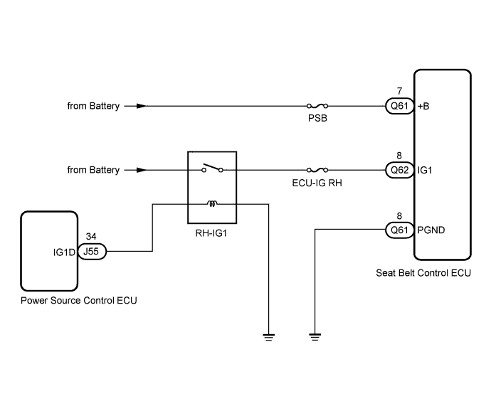
This circuit supplies power to the seat belt control ECU.
WIRING DIAGRAM
INSPECTION PROCEDURE
Note
When the seat belt control ECU is replaced with a new one, Initialization must be performed Click here.
PROCEDURE
-
INSPECT SEAT BELT CONTROL ECU (+B TERMINAL VOLTAGE)
-
Disconnect the negative (-) terminal cable from the battery.
CAUTION:
Wait at least 90 seconds after disconnecting the cable from the negative (-) battery terminal to disable the SRS system.
Note
When disconnecting the cable, some system need to be initialized after the cable is reconnected Click here.
-
Disconnect the Q61 seat belt control ECU connector.
-
Connect the negative (-) terminal cable to the battery.
-
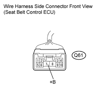
Measure the voltage according to the value(s) in the table below.
Standard voltage Tester Connection Condition Specified Condition Q61-7 (+B) - Body ground Always 11 to 14 V -
Disconnect the negative (-) terminal cable from the battery.
-
Reconnect the Q61 seat belt control ECU connector.
-
Connect the negative (-) terminal cable to the battery.
NG 
INSPECT FUSE (PSB FUSE) Click here
OK 
-
-
INSPECT SEAT BELT CONTROL ECU (IG1 TERMINAL VOLTAGE)
-
Disconnect the negative (-) terminal cable from the battery.
CAUTION:
Wait at least 90 seconds after disconnecting the cable from the negative (-) battery terminal to disable the SRS system.
Note
When disconnecting the cable, some system need to be initialized after the cable is reconnected Click here.
-
Disconnect the Q62 seat belt control ECU connector.
-
Connect the negative (-) terminal cable to the battery.
-
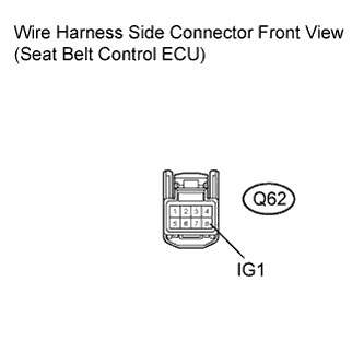
Measure the voltage according to the value(s) in the table below.
Standard voltage Tester Connection Condition Specified Condition Q62-8 (IG1) - Body ground Engine switch on (IG) 10 to 14 V Q62-8 (IG1) - Body ground Engine switch off Below 1 V -
Disconnect the negative (-) terminal cable from the battery.
-
Reconnect the Q62 seat belt control ECU connector.
-
Connect the negative (-) terminal cable to the battery.
NG
INSPECT FUSE (ECU-IG RH FUSE) Click here
OK
-
-
INSPECT SEAT BELT CONTROL ECU (PGND CIRCUIT)
-
Disconnect the negative (-) terminal cable from the battery.
CAUTION:
Wait at least 90 seconds after disconnecting the cable from the negative (-) battery terminal to disable the SRS system.
Note
When disconnecting the cable, some system need to be initialized after the cable is reconnected Click here.
-
Disconnect the Q61 seat belt control ECU connector.
-
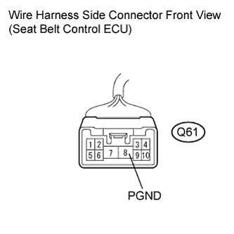
Measure the resistance according to the value(s) in the table below.
Standard resistance Tester Connection Condition Specified Condition Q61-8 (PGND) - Body ground Always Below 1 Ω -
Reconnect the Q61 seat belt control ECU connector.
-
Connect the negative (-) terminal cable to the battery.
NG 
REPAIR OR REPLACE HARNESS OR CONNECTOR (PGND CIRCUIT)
OK 
REPLACE SEAT BELT CONTROL ECU Click here
-
-
INSPECT FUSE (PSB FUSE)
-
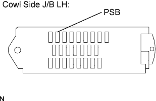
Remove the PSB fuse from the cowl side J/B LH.
-
Measure the resistance according to the value(s) in the table below.
Standard resistance Tester Connection Condition Specified Condition PSB fuse Always Below 1 Ω -
Reinstall the PSB fuse to the cowl side J/B LH.
NG
REPLACE FUSE (PSB FUSE)
OK
REPAIR OR REPLACE HARNESS OR CONNECTOR (SEAT BELT CONTROL ECU - BATTERY)
-
-
INSPECT FUSE (ECU-IG RH FUSE)
-
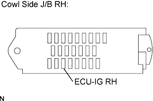
Remove the ECU-IG RH fuse from the cowl side J/B RH.
-
Measure the resistance according to the value(s) in the table below.
Standard resistance Tester Connection Condition Specified Condition ECU-IG RH fuse Always Below 1 Ω -
Reinstall the ECU-IG RH fuse to the cowl side J/B RH.
NG
REPLACE FUSE (ECU-IG RH FUSE)
OK
REPAIR OR REPLACE HARNESS OR CONNECTOR (SEAT BELT CONTROL ECU - RH IG1 RELAY)
-