PRE-CRASH SAFETY SYSTEM, Diagnostic DTC:B2005

| DTC Code | DTC Name |
|---|---|
| B2005 | Short to B+ in Seat Belt Motor LH Circuit |
DESCRIPTION
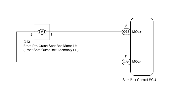
The seat belt control ECU receives information from the distance control ECU using CAN communication and tightens the seat belt by operating the motor in the front seat outer belt assembly LH.
CAUTION:
The pretensioner is built into the front seat outer belt assembly LH. Be sure to follow the correct inspection procedure, as failure to follow the correct procedure (such as inspection of incorrect connectors) may deploy the pretensioner.
| DTC No. | DTC Detection Condition | Trouble Area |
|---|---|---|
| B2005 |
|
|
WIRING DIAGRAM
INSPECTION PROCEDURE
Note
When the seat belt control ECU is replaced with a new one, Initialization must be performed Click here.
PROCEDURE
-
INSPECT FRONT SEAT OUTER BELT ASSEMBLY LH
-
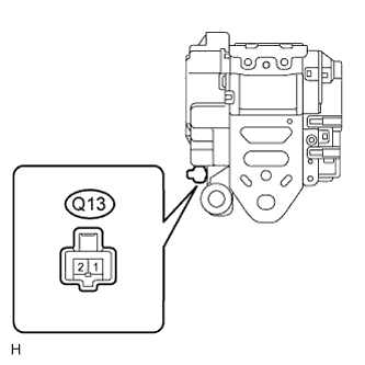
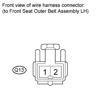
Disconnect the Q13 connector of the front seat outer belt assembly LH.
-
Measure the voltage according to the value(s) in the table below.
Standard Voltage Tester Connection Condition Specified Condition Q13-1 - Body ground Engine switch on (IG) Below 1 V Q13-2 - Body ground Engine switch on (IG) Below 1 V
NG 
REPLACE FRONT SEAT OUTER BELT ASSEMBLY LH Click here
OK 
-
-
CHECK HARNESS AND CONNECTOR (FRONT SEAT OUTER BELT ASSEMBLY LH - SEAT BELT CONTROL ECU)
-
Disconnect the cable from the negative (-) battery terminal.
CAUTION:
Wait at least 90 seconds after disconnecting the cable from the negative (-) battery terminal to disable the SRS system.
Note
When disconnecting the cable, some systems need to be initialized after the cable is reconnected Click here.
-
Disconnect the Q38 connector of the seat belt control ECU.
-
Connect the cable to the negative battery terminal.
-
Measure the voltage according to the value(s) in the table below.
Standard Voltage Tester Connection Condition Specified Condition Q13-1 - Body ground Engine switch on (IG) Below 1 V Q13-2 - Body ground Engine switch on (IG) Below 1 V
NG
REPAIR OR REPLACE HARNESS OR CONNECTOR
OK 
REPLACE SEAT BELT CONTROL ECU Click here
-