METER / GAUGE SYSTEM Voltage Meter Malfunction
DESCRIPTION
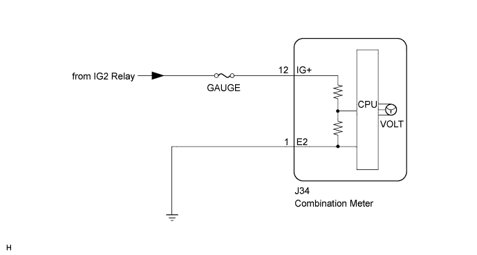
The voltage meter displays the battery voltage using one bar. If the battery voltage is too low (below 10 V), the first bar will blink to inform the driver. If the voltage is too high (17 V or higher), the seventh bar will blink. When turning the engine switch on (IG), the meter CPU determines the battery voltage based on the power source voltage supplied to it.
WIRING DIAGRAM
INSPECTION PROCEDURE
PROCEDURE
-
CHECK HARNESS AND CONNECTOR (POWER SOURCE CIRCUIT)
-
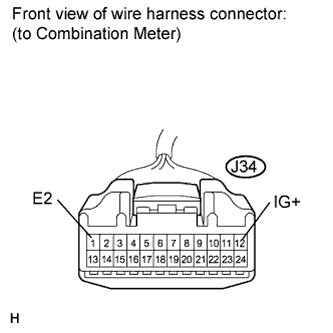
Disconnect the J34 connector.
-
Measure the voltage according to the value(s) in the table below.
Standard Voltage Tester Connection Switch Condition Specified Condition J34-12 (IG+) - Body ground Engine switch on (IG) 11 to 14 V Engine switch off Below 1 V -
Measure the resistance according to the value(s) in the table below.
Standard Resistance Tester Connection Condition Specified Condition J34-1 (E2) - Body ground Always Below 1 Ω
NG 
REPAIR OR REPLACE HARNESS OR CONNECTOR
OK 
REPLACE COMBINATION METER Click here
-