METER / GAUGE SYSTEM Operating Light Control Rheostat does not Change Light Brightness
DESCRIPTION
The meter CPU receives signals for adjusting illumination on the meter and instrument panel from this circuit. The meter CPU detects the illumination level selected by the user according to the position of the rheostat knob.
Tech Tips
-
The meter illumination level can be adjusted by turning the rheostat.
-
The meter illumination dims when the light control switch is turned to the TAIL or HEAD position at night.
-
Turning the rheostat knob fully clockwise cancels the above dimmer control.
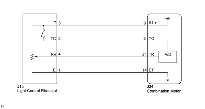
WIRING DIAGRAM
INSPECTION PROCEDURE
PROCEDURE
-
SYSTEM CHECK
Result Result Proceed to Meter illumination does not change when operate the light control rheostat knob A Dimmer function cannot be canceled B
B 
READ VALUE USING INTELLIGENT TESTER (TAIL CANCEL SW) Click here
A 
-
READ VALUE USING INTELLIGENT TESTER (RHEOSTAT VALUE)
-
Connect the intelligent tester to the DLC3.
-
Turn the engine switch on (IG).
-
Turn the intelligent tester on.
-
Enter the following menus: Body / Combination Meter / Data List.
-
Check the values by referring to the table below.
Combination Meter Tester Display Measurement Item/Range Normal Condition Diagnostic Note Light Control Rheostat Light control rheostat/Min.: 0%, Max.: 100% Turn the light control rheostat knob fully counterclockwise (0%) - Turn the light control rheostat knob fully clockwise (100%) OK The value displayed on the intelligent tester gradually changes as the actual rheostat operation.
NG
INSPECT LIGHT CONTROL RHEOSTAT Click here
OK
-
-
READ VALUE USING INTELLIGENT TESTER (TAIL CANCEL SW)
-
Connect the the intelligent tester to the DLC3.
-
Turn the engine switch on (IG).
-
Turn the intelligent tester on.
-
Enter the following menus: Body / Combination Meter / Data List.
-
Check the values by referring to the table below.
Combination Meter Tester Display Measurement Item/Range Normal Condition Diagnostic Note Tail Cancel SW Tail cancel switch is OFF or ON OFF: Light control rheostat position is except below. - ON: Turn the light control rheostat knob fully clockwise (Tail cancel switch is ON) - OK Condition displayed on the intelligent tester is the same as the actual light control rheostat knob position.
NG
INSPECT LIGHT CONTROL RHEOSTAT Click here
OK 
REPLACE COMBINATION METER Click here
-
-
INSPECT LIGHT CONTROL RHEOSTAT
-
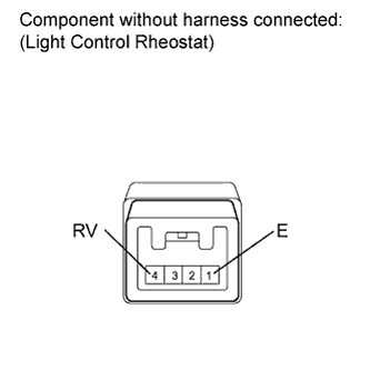
Remove the light control rheostat with the connector still connected.
-
Measure the resistance according to the value(s) in the table below.
Standard Resistance Tester Connection Condition Specified Condition 1 (E) - 4 (RV) Turn the rheostat knob fully clockwise 8 to 12 kΩ 1 (E) - 4 (RV) Rheostat knob is between MIN. and MAX. The value changes gradually
(Between approx. 0 to 8 kΩ)
1 (E) - 4 (RV) Turn the rheostat knob fully counterclockwise Approx. 0 Ω
NG 
REPLACE LIGHT CONTROL RHEOSTAT Click here
OK
-
-
CHECK HARNESS AND CONNECTOR (COMBINATION METER - LIGHT CONTROL RHEOSTAT)
-
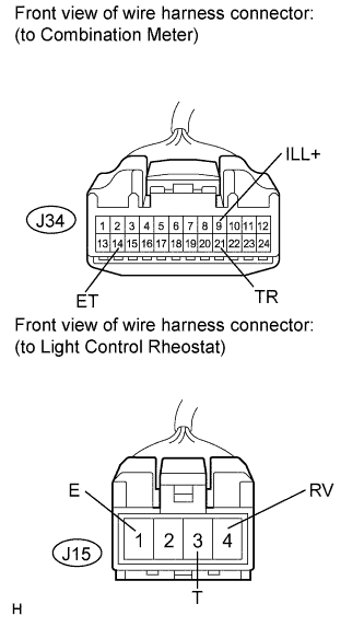
Disconnect the J34 connector.
-
Measure the resistance according to the value(s) in the table below.
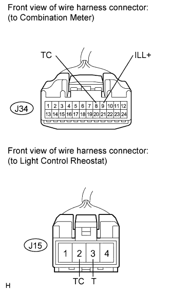
Standard Resistance Tester Connection Condition Specified Condition J34-14 (ET) - J15-1 (E) Always Below 1 Ω J34-9 (ILL+) - J15-3 (T) Always Below 1 Ω J34-21 (TR) - J15-4 (RV) Always Below 1 Ω J15-1 (E) - Body ground Always 10 kΩ or higher J15-3 (T) - Body ground Always 10 kΩ or higher J15-4 (RV) - Body ground Always 10 kΩ or higher
NG
REPAIR OR REPLACE HARNESS OR CONNECTOR
OK
REPLACE COMBINATION METER Click here
-
-
READ VALUE USING INTELLIGENT TESTER (TAIL CANCEL SW)
-
Connect the intelligent tester to the DLC3.
-
Engine switch on (IG).
-
Turn the intelligent tester on.
-
Enter the following menus: Body / Combination Meter / Data List.
-
Check the values by referring to the table below.
Combination Meter Tester Display Measurement Item/Range Normal Condition Diagnostic Note Tail Cancel SW Tail cancel switch is OFF or ON OFF: Light control rheostat position is except below. - ON: Turn the light control rheostat knob fully clockwise (Tail cancel switch is ON) - OK Condition displayed on the intelligent tester is the same as the actual light control rheostat position.
NG
INSPECT LIGHT CONTROL RHEOSTAT Click here
OK
REPLACE COMBINATION METER Click here
-
-
INSPECT LIGHT CONTROL RHEOSTAT
-
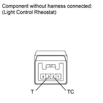
Remove the light control rheostat with connector still connected.
-
Measure the resistance according to the value(s) in the table below.
Standard Resistance Tester Connection Condition Specified Condition 2 (TC) - 3 (T) Turn the light control rheostat knob fully counterclockwise Below 1 Ω 2 (TC) - 3 (T) Turn the light control rheostat knob fully clockwise (Tail cancel switch is ON) 10 kΩ or higher
NG
REPLACE LIGHT CONTROL RHEOSTAT Click here
OK
-
-
CHECK HARNESS AND CONNECTOR (COMBINATION METER - LIGHT CONTROL RHEOSTAT)
-
Disconnect the J34 connector.
-
Measure the resistance according to the value(s) in the table below.
Standard Resistance Tester Connection Condition Specified Condition J34-8 (TC) - J15-2 (TC) Always Below 1 Ω J15-2 (TC) - Body ground Always 10 kΩ or higher J34-9 (ILL+) - J15-3 (T) Always Below 1 Ω J15-3 (T) - Body ground Always 10 kΩ or higher
NG
REPAIR OR REPLACE HARNESS OR CONNECTOR
OK
REPLACE COMBINATION METER Click here
-