METER / GAUGE SYSTEM Tachometer Malfunction
DESCRIPTION
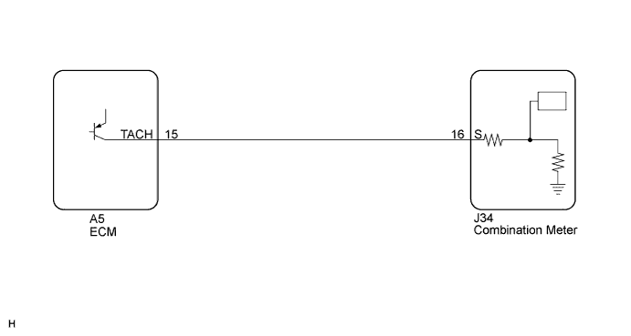
The meter CPU receives engine speed signals from the ECM in this circuit. The ECM transmits engine speed signals as pulses to the meter CPU. The meter CPU calculates the engine speed converting 4 pulses to 2 revolutions.
WIRING DIAGRAM
INSPECTION PROCEDURE
PROCEDURE
-
PERFORM ACTIVE TEST USING INTELLIGENT TESTER (TACHO METER OPERATION)
-
Connect the intelligent tester to the DLC3.
-
Turn the engine switch on (IG).
-
Turn the intelligent tester on.
-
Enter the following menus: Body / Combination Meter / Active Test.
-
Check the operation by referring to the values in the table below.
Combination Meter Tester Display Test Part Control Range Diagnostic Note Tacho Meter Operation Tachometer 0, 1000, 2000, 3000, 4000, 5000, 6000, 7000 (rpm) Confirm that the vehicle is stopped, engine idling OK Tachometer indication is normal.
NG 
REPLACE COMBINATION METER Click here
OK 
-
-
READ VALUE USING INTELLIGENT TESTER (ENGINE RPM)
-
Connect the intelligent tester to the DLC3.
-
Engine start.
-
Turn the intelligent tester on.
-
Enter the following menus: Body / Combination Meter / Data List.
-
Check the values by referring to the values in the table below.
Combination Meter Tester Display Measurement Item/Range Normal Condition Diagnostic Note Engine Rpm Engine speed/Min.: 0 rpm, Max.: 12750 rpm Almost same as actual engine speed (tachometer indication) If data received from the ECM exceeds the range that can be displayed on the meter, the meter continues to display the maximum value of the range. Result Result Proceed to The tachometer indication differs from the engine speed displayed on the intelligent tester. A Engine speed displayed on the intelligent tester is almost the same as the tachometer indication. B Both the tachometer indication and the engine speed displayed on the intelligent tester is 0. C
B 
READ VALUE USING INTELLIGENT TESTER (ENGINE SPEED) Click here
C
CHECK HARNESS AND CONNECTOR (COMBINATION METER - ECM) Click here
A 
REPLACE COMBINATION METER Click here
-
-
READ VALUE USING INTELLIGENT TESTER (ENGINE SPEED)
-
Connect the intelligent tester to the DLC3.
-
Engine start.
-
Turn the intelligent tester on.
-
Enter the following menus: Powertrain / Engine and ECT / Data List.
-
Check the values by referring to the table below.
Engine and ECT Tester Display Measurement Item/Range Normal Condition Diagnostic Note Engine Speed Engine speed/Min.: 0 rpm, Max.: 16383.75 rpm Almost same as actual engine speed (tachometer indication) - OK Engine speed displayed on the intelligent tester is almost the same as the tachometer indication.
NG
GO TO SFI SYSTEM (for 2UR-GSE) Click here
OK
-
-
CHECK HARNESS AND CONNECTOR (COMBINATION METER - ECM)
-
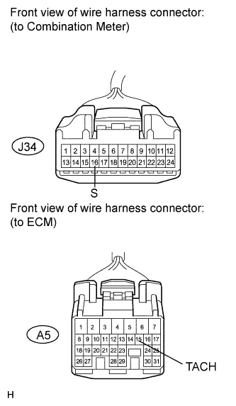
Disconnect the A5 and J34 connectors.
-
Measure the resistance according to the value(s) in the table below.
Standard Resistance Tester Connection Condition Specified Condition A5-15 (TACH) - J34-16 (S) Always Below 1 Ω A5-15 (TACH) - Body ground Always 10 kΩ or higher
NG
REPAIR OR REPLACE HARNESS OR CONNECTOR
OK
-
-
INSPECT ECM (INPUT WAVEFORM)
-
Check the input signal waveform.
-
Reconnect the A5 ECM connector.
-
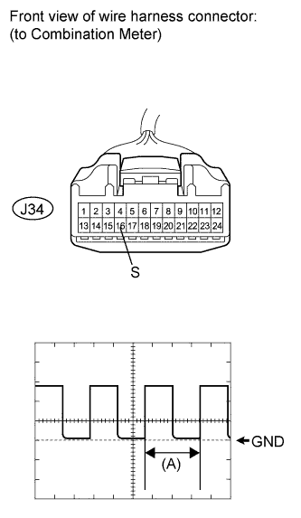
Connect the oscilloscope to the terminal J34-16 (S) and body ground.
-
Start the engine.
-
Check the signal waveform according to the condition(s) in the table below.
Item Condition Tool setting 5 V/DIV., 10 ms./DIV. Vehicle condition Engine idling OK The waveform is displayed as shown in the illustration. Tech Tips
When the system is functioning normally, one engine revolution generates 4 pulses. As the engine speed increases, the width indicated by (A) in the illustration narrows.
-
NG
REPLACE ECM (for 2UR-GSE) Click here
OK
REPLACE COMBINATION METER Click here
-