METER / GAUGE SYSTEM Speedometer Malfunction
DESCRIPTION
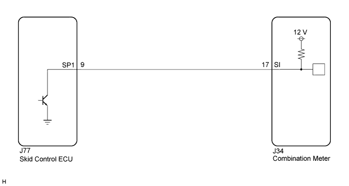
The meter CPU receives vehicle speed signals from this circuit. The speed sensor detects the wheel speed and sends the appropriate signals to the skid control ECU. Skid control ECU supplies power to the vehicle speed sensor. Skid control ECU detects vehicle speed signals based on the pulses of the voltage. Skid control ECU transmits vehicle speed signals as pulses to the meter CPU. The meter CPU calculates the vehicle speed converting 4 pulses to 1 revolution.
Tech Tips
Factors that affect the indicated vehicle speed include tire size, tire inflation, and tire wear. The speed indicated on the speedometer has an allowable margin of error. This can be tested using a speedometer tester (calibrated chassis dynamometer). For details about testing and the margin of error, see the reference chart Click here.
WIRING DIAGRAM
INSPECTION PROCEDURE
Note
If the vehicle speed is outside the allowable range when tested, perform the following procedure Click here.
Tech Tips
Before starting circuit inspection, check tire size and tire pressure.
PROCEDURE
-
PERFORM ACTIVE TEST USING INTELLIGENT TESTER (SPEED METER OPERATION)
-
Connect the intelligent tester to the DLC3.
-
Turn the engine switch on (IG).
-
Turn the intelligent tester on.
-
Enter the following menus: Body / Combination Meter / Active Test.
-
Check the operation by referring to the table below.
Combination Meter Tester Display Test Part Control Range Diagnostic Note Speed Meter Operation Speedometer 0, 40, 80, 120 mph*1 Confirm that the vehicle is stopped, engine idling 0, 40, 80, 120, 160, 200, 240 km/h*2
-
*1: for RHD
-
*2: for LHD
OK Speedometer indication is normal. -
NG 
REPLACE COMBINATION METER Click here
OK 
-
-
READ VALUE USING INTELLIGENT TESTER (VEHICLE SPEED METER)
-
Connect the intelligent tester to the DLC3.
-
Turn the engine switch on (IG).
-
Turn the intelligent tester on.
-
Enter the following menus: Body / Combination Meter / Data List.
-
Check the values by referring to the values in the table below.
Combination Meter Tester Display Measurement Item/Range Normal Condition Diagnostic Note Vehicle Speed Meter Vehicle speed/Min.: 0 km/h (0 mph), Max.: 255 km/h (158 mph) Almost same as actual speed (speedometer tester) - OK Vehicle speed displayed on the intelligent tester is almost the same as the actual vehicle speed measured using a speedometer tester (calibrated chassis dynamometer).
NG 
READ VALUE USING INTELLIGENT TESTER (FL/FR/RL/RR WHEEL SPEED) Click here
OK 
REPLACE COMBINATION METER Click here
-
-
READ VALUE USING INTELLIGENT TESTER (FL/FR/RL/RR WHEEL SPEED)
-
Connect the intelligent tester to the DLC3.
-
Turn the engine switch on (IG).
-
Turn the intelligent tester on.
-
Enter the following menus: Chassis / ABS/VSC/TRC / Data List.
-
Check the values by referring to the table below.
ABS/VSC/TRC Tester Display Measurement Item/Range Normal Condition Diagnostic Note FR Wheel Speed Vehicle speed/Min.: 0 km/h (0 mph), Max.: 326 km/h (202 mph) Almost same as actual speed (speedometer tester) - FL Wheel Speed Vehicle speed/Min.: 0 km/h (0 mph), Max.: 326 km/h (202 mph) Almost same as actual speed (speedometer tester) - RR Wheel Speed Vehicle speed/Min.: 0 km/h (0 mph), Max.: 326 km/h (202 mph) Almost same as actual speed (speedometer tester) - RL Wheel Speed Vehicle speed/Min.: 0 km/h (0 mph), Max.: 326 km/h (202 mph) Almost same as actual speed (speedometer tester) - OK Vehicle speed displayed on the intelligent tester is almost the same as the actual vehicle speed measured using a speedometer tester (calibrated chassis dynamometer).
NG
GO TO BRAKE CONTROL SYSTEM Click here
OK
-
-
INSPECT COMBINATION METER (OUTPUT VOLTAGE)
-
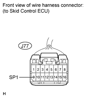
Disconnect the J77 connector.
-
Measure the voltage according to the value(s) in the table below.
Standard Voltage Tester Connection Condition Specified Condition J77-9 (SP1) -
Body ground
Engine switch on (IG) 11 to 14 V
NG
CHECK HARNESS AND CONNECTOR (COMBINATION METER - SKID CONTROL ECU) Click here
OK
-
-
INSPECT SKID CONTROL ECU (INPUT WAVEFORM)
-
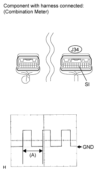
Check the input signal waveform.
-
Remove the combination meter with connector(s) still connected.
-
Reconnect the J77 connector.
-
Connect the oscilloscope to the terminals J34-17 (SI) and body ground.
-
Turn the engine switch on (IG).
-
Turn the drive wheel slowly.
-
Check the signal waveform according to the condition(s) in the table below.
Item Condition Tool setting 5 V/DIV., 20 ms./DIV. Vehicle condition Driving at approx. 20 km/h (12 mph) OK The waveform is displayed as shown in the illustration. Tech Tips
When the system is functioning normally, one drive wheel revolution generates 4 pulses. As the vehicle speed increases, the width indicated by (A) in the illustration narrows.
-
NG
REPLACE SKID CONTROL ECU Click here
OK
REPLACE COMBINATION METER Click here
-
-
CHECK HARNESS AND CONNECTOR (COMBINATION METER - SKID CONTROL ECU)
-
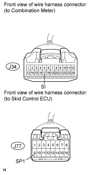
Disconnect the J34 and J77 connectors.
-
Measure the resistance according to the value(s) in the table below.
Standard Resistance Tester Connection Condition Specified Condition J77-9 (SP1) - J34-17 (SI) Always Below 1 Ω J77-9 (SP1) - Body ground Always 10 kΩ or higher
NG
REPAIR OR REPLACE HARNESS OR CONNECTOR
OK
REPLACE COMBINATION METER Click here
-