METER / GAUGE SYSTEM TERMINALS OF ECU

-
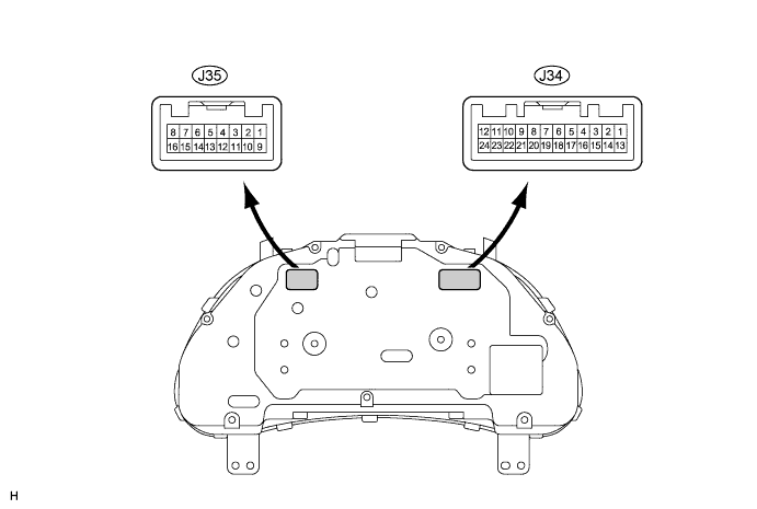
COMBINATION METER
-
Measure the voltage according to the value(s) in the table below.
Terminal No. (Symbol) Wiring Color Terminal Description Condition Specified Condition J34-1 (E2) - Body ground W-B - Body ground Ground Always Below 1 V J34-2 (FE) - Body ground BR - Body ground Ground (Fuel ground) Always Below 1 V J34-3 (GND) - Body ground W - Body ground Ground (Engine oil temperature sensor ground) Always Below 1 V J34-5 (+S) - Body ground P - Body ground Speed signal (Output) Turn the wheel slowly Pulse generation
(See waveform 1)
J34-6 (MPX+) - Body ground BR - Body ground Multiplex communication signal Engine switch on (IG) Pulse generation J34-7 (GAGE) - Body ground L - Body ground Engine oil temperature sensor signal Engine switch on (IG), engine oil temperature is about 0°C (32°F) 4 to 6 V Engine switch on (IG), engine oil temperature is about 100°C (212°F) 0.5 to 2.5 V J34-8 (TC) - Body ground P - Body ground Light control rheostat signal Engine switch on (IG), the light control rheostat knob is at the MAX. position (turns fully clockwise) 4 to 6 V Engine switch on (IG), the light control rheostat knob is at the MIN. position (turns fully counterclockwise) Below 1 V J34-9 (ILL+) - Body ground V - Body ground Light control rheostat signal Engine switch on (IG), combination switch is except on OFF 4 to 6 V J34-11 (B) - Body ground G - Body ground Turn indicator light signal Engine switch on (IG), turn signal LH indicator light OFF Below 1 V Engine switch on (IG), turn signal LH indicator light blinks 11 to 14 V J34-12 (IG+) - Body ground O - Body ground Engine switch signal Engine switch off Below 1 V Engine switch on (IG) 11 to 14 V J34-13 (ES) - Body ground W-B - Body ground Ground (Signal ground) Always Below 1 V J34-14 (ET) - Body ground Y - Body ground Ground (Rheostat ground) Always Below 1 V J34-16 (S) - Body ground W - Body ground Tachometer signal Engine switch on (IG), engine idle speed Pulse generation
(See waveform 2)
J34-17 (SI) - Body ground V - Body ground Speed signal (Input) Engine switch on (IG), turn the wheel slowly Pulse generation
(See waveform 1)
J34-18 (MPX-) - Body ground BR - Body ground Multiplex communication signal Engine switch on (IG) Pulse generation J34-19 (FR) - Body ground SB - Body ground Fuel signal Engine switch on (IG), fuel level is FULL Below 1 V Engine switch on (IG), fuel level is EMPTY 4 to 7 V J34-20 (MSSL) - Body ground Y - Body ground Steering pad switch signal Engine switch on (IG), DISP switch is not pressed 4 to 6 V Engine switch on (IG), DISP switch is pressed Below 1 V J34-21 (TR) - Body ground B - Body ground Light control rheostat signal Engine switch on (IG), the light control rheostat knob is at the MIN. position (turns fully counterclockwise). Below 1 V Engine switch on (IG), the light control rheostat knob is at the MAX. position (turns fully clockwise). 4 to 6 V J34-23 (B) - Body ground L - Body ground Battery Always 11 to 14 V J34-24 (B) - Body ground LG - Body ground Battery Always 11 to 14 V J35-3 (PBLT) - Body ground P - Body ground Front seat inner belt assembly (for passenger side) signal Sit in the front passenger seat, engine switch on (IG), front passenger side seat belt is unfastened 11 to 14 V Sit in the front passenger seat, engine switch on (IG), front passenger side seat belt is fastened Below 1 V J35-4 (P/SB) - Body ground L - Body ground Passenger seat belt warning light signal Sit in the passenger seat, engine switch on (IG), front passenger side seat belt warning light OFF 11 to 14 V Sit in the passenger seat, engine switch on (IG), front passenger side seat belt warning light blinks Pulse generation (See waveform 3) J35-5 (RSEL) - Body ground GR - Body ground Satellite switch RH signal Engine switch on (IG), satellite switch RH is not pressed 11 to 14 V Engine switch on (IG), satellite switch RH is pressed Below 1 V J35-6 (LSEL) - Body ground O - Body ground Satellite switch LH signal Engine switch on (IG), satellite switch LH is not pressed 11 to 14 V Engine switch on (IG), satellite switch LH is pressed Below 1 V J35-7 (SET) - Body ground V - Body ground Satellite switch ON/OFF signal Engine switch on (IG), satellite switch ON/OFF is not pressed 11 to 14 V Engine switch on (IG), satellite switch ON/OFF is pressed Below 1 V J35-9 (ILL-) - Body ground W - Body ground Illumination signal Engine switch on (IG) 11 to 14 V J35-10 (B) - Body ground R - Body ground Turn indicator light signal Engine switch on (IG), turn signal RH indicator light OFF Below 1 V Engine switch on (IG), turn signal RH indicator light blinks 11 to 14 V J35-12 (EFI) - Body ground SB - Body ground MIL (Check engine indicator light) signal Engine switch on (IG), MIL ON Below 1 V Engine switch on (IG), MIL OFF 11 to 14 V J35-15 (SW) - Body ground LG - Body ground Brake fluid level warning light signal Engine switch on (IG), brake warning light OFF 11 to 14 V Engine switch on (IG), brake warning light ON Below 1.5 V -
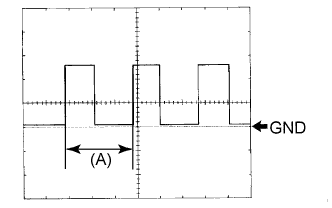
Waveform 1 (Reference) : Using an oscilloscope:
OK: Item Condition Tool setting 5 V/DIV., 20 ms./DIV. Vehicle condition Driving at approx. 20 km/h (12 mph) Tech Tips
When the system is functioning normally, one drive wheel revolution generates 4 pulses. As the vehicle speed increases, the width indicated by (A) in the illustration narrows.
-
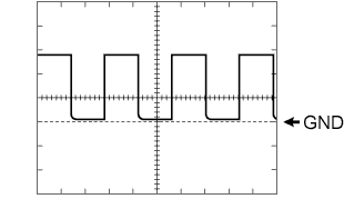
Waveform 2 (Reference) : Using an oscilloscope:
OK: Item Condition Tool setting 5 V/DIV., 10 ms./DIV. Vehicle condition Engine idle speed -
Waveform 3 (Reference) : Using an oscilloscope:
OK: Item Condition Tool setting 5 V/DIV., 200 ms./DIV. Vehicle condition Engine switch on (IG), p-belt warning light blinks
-
-
CLOCK ASSEMBLY (w/o Navigation System)

-
Measure the voltage according to the value(s) in the table below.
Terminal No. (Symbol) Wiring Color Terminal Description Condition Specified Condition J54-3 (ILL+) - Body ground G - Body ground Illumination signal Combination switch OFF Below 1 V Combination switch Head 11 to 14 V J54-4 (IG+) - Body ground B - Body ground Engine switch signal Engine switch off Below 1 V Engine switch on (IG) 11 to 14 V J54-5 (ACC) - Body ground O - Body ground Engine switch signal Engine switch off Below 1 V Engine switch on (IG) 11 to 14 V J54-8 (E) - Body ground W-B - Body ground Ground Always Below 1 V J54-10 (ILL-) - Body ground W - Body ground Illumination Signal Engine switch on (IG), combination switch Head, and light control rheostat position MAX. Pulse generation
(See waveform)
J54-14 (B) - Body ground LG - Body ground Battery Always 11 to 14 V -
Waveform (Reference) : Using an oscilloscope:
OK: Item Condition Tool setting 5 V/DIV., 200 ms./DIV. Vehicle condition Engine switch on (IG), light control rheostat is in the MID. position.
-
-
CLOCK ASSEMBLY (w/ Navigation System)

-
Measure the voltage according to the value(s) in the table below.
Terminal No. (Symbol) Wiring Color Terminal Description Condition Specified Condition J53-2 (E) - Body ground W-B - Body ground Ground Always Below 1 V J53-4 (ILL+) - Body ground G - Body ground Illumination signal Combination switch OFF Below 1 V Combination switch Head 11 to 14 V J53-5 (ACC) - Body ground O - Body ground Engine switch signal Engine switch off Below 1 V Engine switch on (IG) 11 to 14 V J53-6 (B) - Body ground LG - Body ground Battery Always 11 to 14 V J53-10 (ILL-) - Body ground W - Body ground Illumination signal Engine switch on (IG), combination switch Head, and light control rheostat position MAX. Pulse generation
(See waveform)
J53-11 (IG+) - Body ground B - Body ground Engine switch signal Engine switch off Below 1 V Engine switch on (IG) 11 to 14 V -
Waveform (Reference) : Using an oscilloscope:
OK: Item Condition Tool setting 5 V/DIV., 200 ms./DIV. Vehicle condition Engine switch on (IG), light control rheostat is in the MID. position.
-
-
COMBINATION METER INNER CIRCUIT
-
Combination Meter Inner Circuit
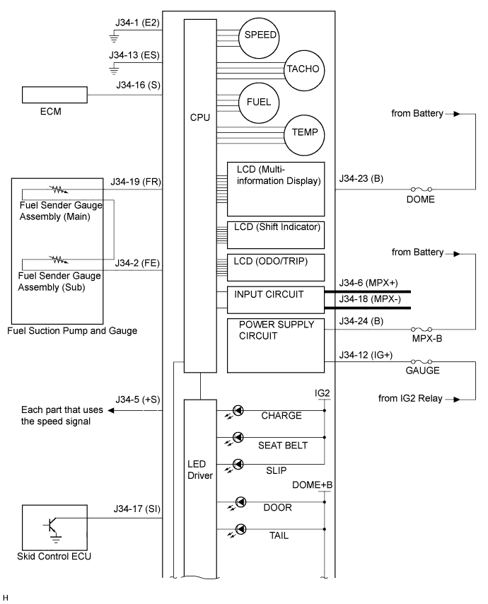
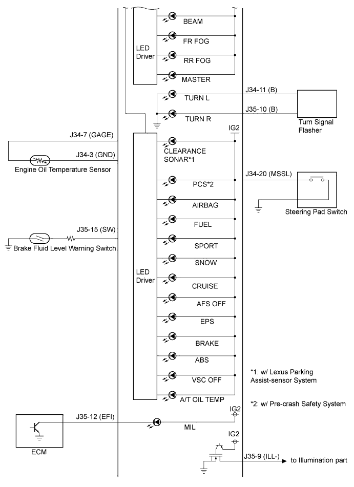
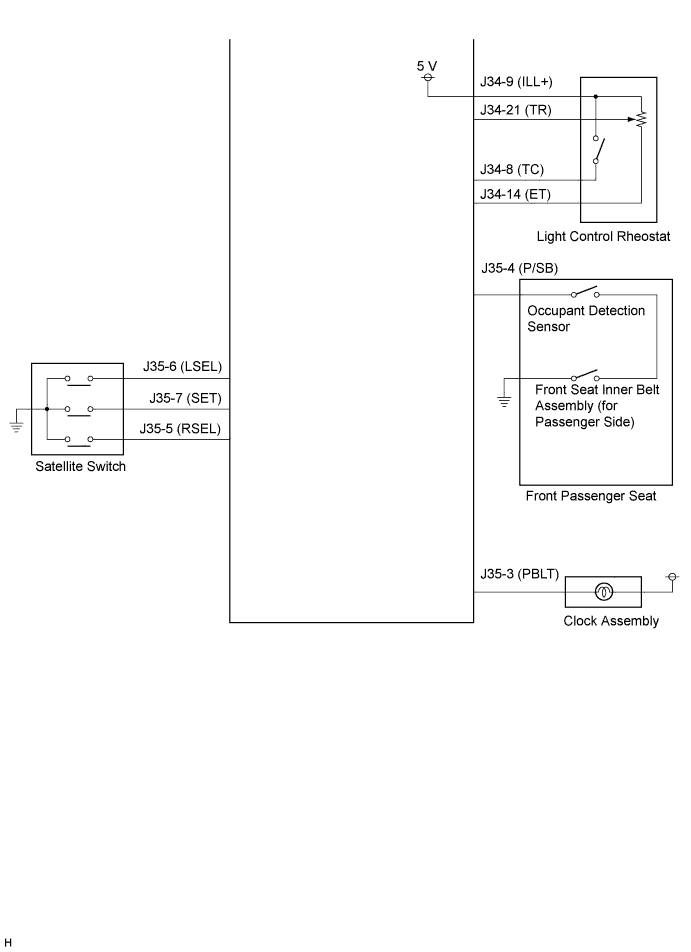
Terminal No. Wire Harness Side (Symbol) J34 1 Ground (E2) 2 Fuel Sender Gauge Assembly (Sub) (FE) 3 Engine Oil Temperature Sensor (GND) 4 - 5 Each part that uses speed signal (+S) 6 Multiplex Communication Line (MPX+) 7 Engine Oil Temperature Sensor (GAGE) 8 Light Control Rheostat (TC) 9 Light Control Rheostat (ILL+) 10 - 11 Turn Signal Flasher (B) 12 GAUGE Fuse (IG+) 13 Ground (ES) 14 Light Control Rheostat (ET) 15 - 16 ECM (S) 17 Skid Control ECU (SI) 18 Multiplex Communication Line (MPX-) 19 Fuel Sender Gauge Assembly (FR) 20 Steering Pad Switch (MSSL) 21 Light Control Rheostat (TR) 22 - 23 DOME Fuse (B) 24 MPX-B Fuse (B) J35 1 - 2 - 3 Clock Assembly (PBLT) 4 Front Passenger Side Seat Belt Inner Belt Assembly (P/SB) 5 Satellite Switch (RSEL) 6 Satellite Switch (LSEL) 7 Satellite Switch (SET) 8 - 9 Illumination Parts (ILL-) 10 Turn Signal Flasher (B) 11 - 12 ECM (EFI) 13 - 14 - 15 Brake Fluid Level Warning Switch (SW) 16 -
-