LIGHTING SYSTEM TERMINALS OF ECU

-
CHECK MAIN BODY ECU RH (COWL SIDE JUNCTION BLOCK RH)
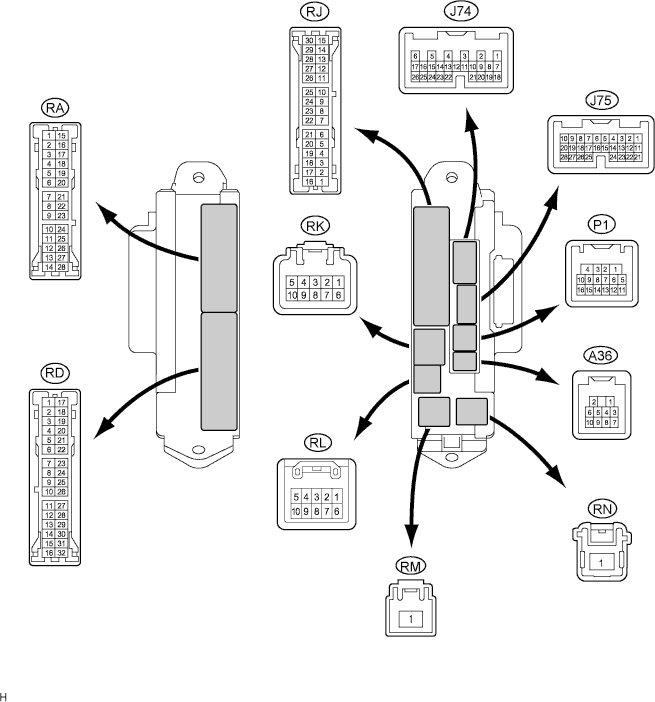
Terminal No. (Symbol) Wiring Color Terminal Description Condition Specified Condition RD-7 (GND2) - Body ground W-B - Body ground Ground Always Below 1 V RA-11 (LCTY) - Body ground BR - Body ground Illumination signal
(From rear door courtesy switch LH)
Rear LH door is closed 11 to 14 V RA-11 (LCTY) - Body ground BR - Body ground Illumination signal
(From rear door courtesy switch LH)
Rear LH door is open Below 1 V RA-20 (MPX1) - Body ground GR - Body ground Multiplex communication signal circuit Engine switch on (IG) Signal waveform RK-5 (BECU) - Body ground G-R - Body ground Multiplex communication power source circuit Always 11 to 14 V P1-14 (DCTY) - Body ground W - Body ground Illumination signal
(From driver side courtesy switch)
Driver's side door is closed 11 to 14 V P1-14 (DCTY) - Body ground W - Body ground Illumination signal
(From driver side courtesy switch)
Driver's side door is open Below 1 V P1-16 (RCTY) - Body ground O - Body ground Illumination signal
(From rear door courtesy switch RH)
Rear RH door is closed 11 to 14 V P1-16 (RCTY) - Body ground O - Body ground Illumination signal
(From rear door courtesy switch RH)
Rear RH door is open Below 1 V J75-15 (FSPT) - Body ground R - Body ground Illumination signal
(To footwell lights)
Footwell lights come on Below 1 V J75-15 (FSPT) - Body ground R - Body ground Illumination signal
(To footwell lights)
Footwell lights go off 11 to 14 V J75-21 (MPX2) - Body ground GR - Body ground Multiplex communication signal circuit Engine switch on (IG) Signal waveform RA-15 (ALTB) - Body ground SB - Body ground Power source circuit Always 11 to 14 V J75-4 (UL2) - Body ground O - Body ground Interior light switch (ON/OFF) signal Interior light switch on Below 1 V J75-4 (UL2) - Body ground O - Body ground Interior light switch (ON/OFF) signal Interior light switch off 11 to 14 V J75-24 (PCYL) - Body ground Y - Body ground Illumination signal
(From front door courtesy light LH)
Passenger's side door is open Below 1 V J75-24 (PCYL) - Body ground Y - Body ground Illumination signal
(From front door courtesy light LH)
Passenger's side door is closed 11 to 14 V P1-13 (DCYL) - Body ground G - Body ground Illumination signal
(From front door courtesy light RH)
Driver's side door is open Below 1 V P1-13 (DCYL) - Body ground G - Body ground Illumination signal
(From front door courtesy light RH)
Driver's side door is closed 11 to 14 V J75-25 (LGCY) - Body ground L - Body ground Illumination signal
(From luggage door courtesy switch)
Luggage door is open Below 1 V J75-25 (LGCY) - Body ground L - Body ground Illumination signal
(From luggage door courtesy switch)
Luggage door is closed 11 to 14 V J75-23 (PCTY) - Body ground B*1 - Body ground
V*2 - Body ground
Illumination signal
(From front door courtesy switch LH)
Passenger's side door is open Below 1 V J75-23 (PCTY) - Body ground B*1 - Body ground
V*2 - Body ground
Illumination signal
(From front door courtesy switch LH)
Passenger's side door is closed 11 to 14 V Tech Tips
-
*1: for LHD
-
*2: for RHD
-
-
CHECK MAIN BODY ECU LH (COWL SIDE JUNCTION BLOCK LH)
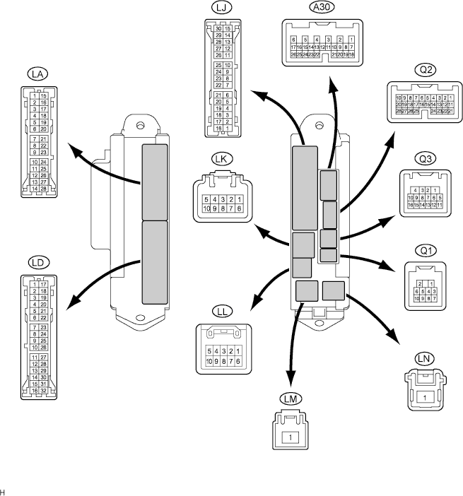
Terminal No. (Symbol) Wiring Color Terminal Description Condition Specified Condition LD-3 (GND) - Body ground W-B - Body ground Ground Always Below 1 V LD-8 (SGND) - Body ground W-B - Body ground Ground Always Below 1 V LD-9 (SGND) - Body ground W-B - Body ground Ground Always Below 1 V LD-18 (MPXB) - Body ground LG - Body ground Multiplex communication power source circuit Always 11 to 14 V Q1-2 (ILE) - Body ground V - Body ground Illumination signal
(To front interior light)
Interior light switch in DOOR position and interior lights come on Below 1 V Q1-2 (ILE) - Body ground V - Body ground Illumination signal
(To front interior light)
Interior light switch in DOOR position and interior lights go off 11 to 14 V Q1-3 (RCTY) - Body ground R - Body ground Illumination signal
(To shift illumination)
Shift illumination comes on Below 1 V Q1-3 (RCTY) - Body ground R - Body ground Illumination signal
(To shift illumination)
Shift illumination goes off 11 to 14 V Q3-15 (MPX1) - Body ground GR - Body ground Multiplex communication signal circuit Engine switch on (IG) Signal waveform A30-17 (MPX2) - Body ground GR - Body ground Multiplex communication signal circuit Engine switch on (IG) Signal waveform Q3-3 (LGCY) - Body ground W - Body ground Illumination signal (to seat illumination) Seat illumination comes on Below 1 V Q3-3 (LGCY) - Body ground W - Body ground Illumination signal (to seat illumination) Seat illumination goes off 11 to 14 V Q3-11 (BDCY) - Body ground P - Body ground Interior light switch (Door) signal Interior light switch on Below 1 V Q3-11 (BDCY) - Body ground P - Body ground Interior light switch (Door) signal Interior light switch off 11 to 14 V -
CHECK OVERHEAD JUNCTION BLOCK
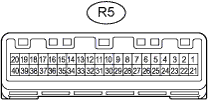
Terminal No. (Symbol) Wiring Color Terminal Description Condition Specified Condition R5-1 (+B1) - Body ground L - Body ground Power source circuit Always 11 to 14 V R5-3 (RRMP) - Body ground O - Body ground Rear personal light power source circuit Always 11 to 14 V R5-4 (ILLB) - Body ground L - Body ground Rear interior light power source circuit Always 11 to 14 V R5-12 (CTY) - Body ground W - Body ground Seat illumination light circuit Seat illumination goes off 11 to 14 V R5-12 (CTY) - Body ground W - Body ground Seat illumination light circuit Seat illumination comes on Below 1 V R5-13 (ILL) - Body ground BR - Body ground Interior light circuit Interior lights go off 11 to 14 V R5-13 (ILL) - Body ground BR - Body ground Interior light circuit Interior lights come on Below 1 V R5-14 (SHFT) - Body ground Y - Body ground Shift illumination circuit Shift illumination goes off 11 to 14 V R5-14 (SHFT) - Body ground Y - Body ground Shift illumination circuit Shift illumination comes on Below 1 V R5-18 (GND3) - Body ground W-B - Body ground Ground Always Below 1 V R5-19 (RGND) - R5-18 (GND3) W-B - W-B Interior light ground Always Below 1 V R5-32 (LILL) - R5-12 (CTY) B - W Seat illumination circuit Always Below 1 Ω R5-33 (RILL) - R5-13 (ILL) P - BR Interior light circuit Always Below 1 Ω R5-34 (CILL) - R5-18 (GND3) P - W-B Interior light switch (ON/OFF) circuit Interior light switch off 11 to 14 V R5-34 (CILL) - R5-18 (GND3) P - W-B Interior light switch (ON/OFF) circuit Interior light switch on Below 1 V R5-35 (DOOR) - R5-18 (GND3) G - W-B Interior light switch (DOOR) circuit Interior light switch off 11 to 14 V R5-35 (DOOR) - R5-18 (GND3) G - W-B Interior light switch (DOOR) circuit Interior light switch on Below 1 V R5-36 (MPX) - Body ground GR - Body ground Multiplex communication signal circuit Engine switch on (IG) Signal waveform