THEFT DETERRENT SYSTEM, Diagnostic DTC:B2763

| DTC Code | DTC Name |
|---|---|
| B2763 | Intrusion Sensor +B Circuit Malfunction (GND Short) |
DESCRIPTION
-
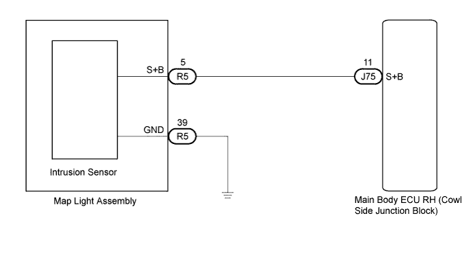
This DTC is output when the S+B line, which is the power supply line to the sensor, is shorted.
| DTC No. | DTC Detection Condition | Trouble Area |
|---|---|---|
| B2763 | S+B line is shorted |
|
WIRING DIAGRAM
INSPECTION PROCEDURE
PROCEDURE
-
CHECK MAIN BODY ECU RH (COWL SIDE JUNCTION BLOCK RH)
-
Measure the voltage according to the value(s) in the table below.
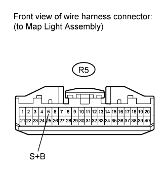
Standard Voltage Tester Connection Condition Specified Condition R5-5 (S+B) - Body ground Theft deterrent system is set. 11 to 14 V
NG 
CHECK HARNESS AND CONNECTOR (MAIN BODY ECU RH - MAP LIGHT ASSEMBLY) Click here
OK 
-
-
CHECK HARNESS AND CONNECTOR (MAP LIGHT ASSEMBLY - BODY GROUND)
-
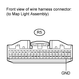
Disconnect R5 map light connector.
-
Measure the Resistance according to the value(s) in the table below.
Standard Resistance Tester Connection Condition Specified Condition R5-39 (GND) - Body ground Always Below 1 Ω
NG 
REPAIR OR REPLACE HARNESS OR CONNECTOR
OK
-
-
REPLACE MAP LIGHT ASSEMBLY
-
Replace the map light assembly Click here.
NEXT
-
-
CHECK FOR DTC
-
Clear the DTC Click here.
-
Check for DTC B2763 again.
OK DTC B2763 is not output.
NG
REPLACE MAIN BODY ECU RH (COWL SIDE JUNCTION BLOCK RH)
OK 
END
-
-
CHECK HARNESS AND CONNECTOR (MAIN BODY ECU RH - MAP LIGHT ASSEMBLY)
-
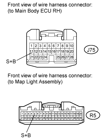
Disconnect the J75 main body ECU RH connector and R5 map light assembly connector.
-
Measure the resistance according to the value(s) in the table below.
Standard Resistance Tester Connection Condition Specified Condition J75-11 (S+B) - R5-5 (S+B) Always Below 1 Ω J75-11 (S+B) - Body ground Always 10 kΩ or higher
NG
REPAIR OR REPLACE HARNESS OR CONNECTOR
OK
REPLACE MAIN BODY ECU RH (COWL SIDE JUNCTION BLOCK RH)
-