ENGINE IMMOBILISER SYSTEM Certification ECU Power Source Circuit
DESCRIPTION
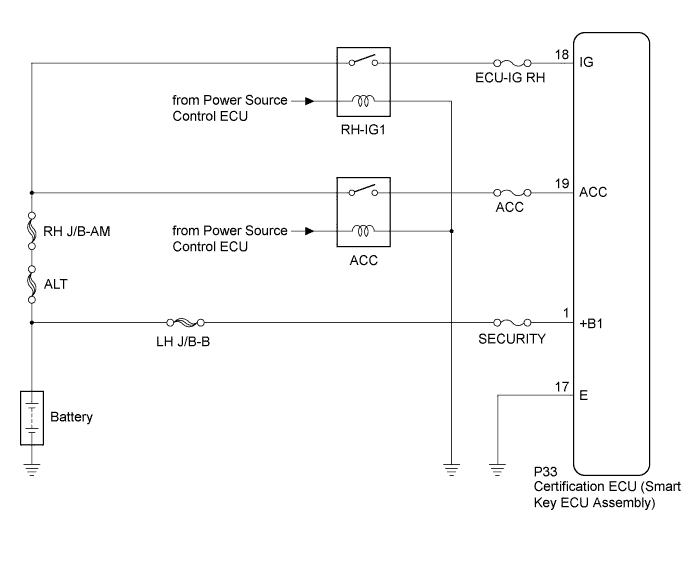
This is the power source circuit of the certification ECU (smart key ECU assembly).
The certification ECU (smart key ECU assembly) controls the following:
-
Key verification confirmation
-
Indoor, outside and door oscillator control
-
Entry door LOCK/UNLOCK request to the main body ECU RH (cowl side junction block RH)
-
Steering LOCK/UNLOCK request
-
Immobiliser SET/UNSET request to the ID code box (immobiliser code ECU)
WIRING DIAGRAM
INSPECTION PROCEDURE
Note
If the certification ECU (smart key ECU assembly) is replaced, register the key.
PROCEDURE
-
CHECK HARNESS AND CONNECTOR (CERTIFICATION ECU - BATTERY)
-
Disconnect the certification ECU (smart key ECU assembly) connector.
-
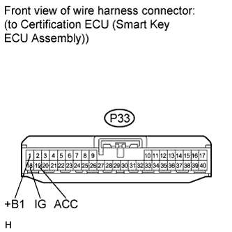
Measure the voltage according to the value(s) in the table below.
Standard Voltage Tester Connection Condition Specified Condition P33-1 (+B1) - Body ground Always 11 to 14 V P33-18 (IG) - Body ground Engine switch off Below 1 V P33-18 (IG) - Body ground Engine switch on (IG) 11 to 14 V P33-19 (ACC) - Body ground Engine switch off Below 1 V P33-19 (ACC) - Body ground Engine switch on (ACC) 11 to 14 V
NG 
REPAIR OR REPLACE HARNESS OR CONNECTOR, OR REPLACE FUSE
OK 
-
-
CHECK HARNESS AND CONNECTOR (CERTIFICATION ECU - BODY GROUND)
-
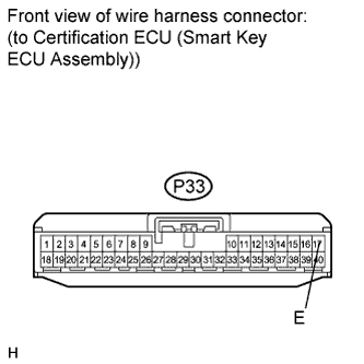
Measure the resistance according to the value(s) in the table below.
Standard Resistance Tester Connection Condition Specified Condition P33-17 (E) - Body ground Always Below 1 Ω
NG
REPAIR OR REPLACE HARNESS OR CONNECTOR
OK 
PROCEED TO NEXT INSPECTION PROCEDURE SHOWN IN PROBLEM SYMPTOMS TABLE Click here
-