ENGINE IMMOBILISER SYSTEM, Diagnostic DTC:B278A

| DTC Code | DTC Name |
|---|---|
| B278A | Short to GND in Immobiliser System Power Source Circuit |
DESCRIPTION
This DTC is output when the engine switch power source supply line is open or shorted.
| DTC No. | DTC Detection Condition | Trouble Area |
|---|---|---|
| B278A | Engine switch power source supply line is open or shorted |
|
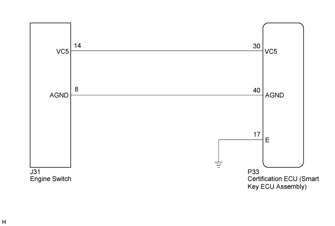
WIRING DIAGRAM
INSPECTION PROCEDURE
Note
If the certification ECU (smart key ECU assembly) is replaced, register the key.
PROCEDURE
-
CHECK DTC OUTPUT
-
Clear the DTCs Click here.
-
Recheck for DTCs.
OK B278A output does not recur.
NG 
CHECK HARNESS AND CONNECTOR (CERTIFICATION ECU - ENGINE SWITCH) Click here
OK 
USE SIMULATION METHOD TO CHECK Click here
-
-
CHECK HARNESS AND CONNECTOR (CERTIFICATION ECU - ENGINE SWITCH)
-
Disconnect the certification ECU (smart key ECU assembly) connector.
-
Disconnect the engine switch connector.
-
Measure the resistance according to the value(s) in the table below.
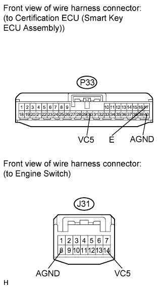
Standard Resistance Tester Connection Condition Specified Condition P33-30 (VC5) - J31-14 (VC5) Always Below 1 Ω P33-40 (AGND) - J31-8 (AGND) Always Below 1 Ω P33-17 (E) - Body ground Always Below 1 Ω P33-30 (VC5) - Body ground Always 10 kΩ or higher P33-40 (AGND) - Body ground Always 10 kΩ or higher
NG 
REPAIR OR REPLACE HARNESS OR CONNECTOR
OK 
-
-
CHECK HARNESS AND CONNECTOR (ENGINE SWITCH POWER SOURCE AND BODY GROUND)
-
Reconnect the certification ECU (smart key ECU assembly) connector.
-
Reconnect the engine switch connector.
-
Measure the voltage according to the value(s) in the table below.
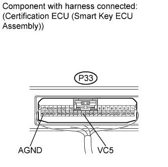
Standard Voltage Tester Connection Condition Specified Condition P33-30 (VC5) - Body ground Key is not in cabin Below 1 V P33-30 (VC5) - Body ground Brake pedal is depressed 4.6 to 5.4 V -
Measure the resistance according to the value(s) in the table below.
Standard Resistance Tester Connection Condition Specified Condition P33-40 (AGND) - Body ground Always Below 1 Ω
NG
REPLACE CERTIFICATION ECU (SMART KEY ECU ASSEMBLY)
OK
REPLACE ENGINE SWITCH Click here
-