ENTRY AND START SYSTEM (for Start Function) Engine does not Start
DESCRIPTION
-
ENGINE START SYSTEM FUNCTION
-
If the engine switch is pressed with the shift lever is in the P or N position and the brake pedal depressed, the power source control ECU determines that it is an engine start request.
-
The certification ECU (smart key ECU assembly) and other ECUs perform key verification via the LIN communication line.
-
The power source control ECU activates the ACC relay.
-
The power source control ECU activates the IG1 and IG2 relays.
-
The certification ECU (smart key ECU assembly) outputs a steering UNLOCK signal. The signal is sent to the power source control ECU via the steering lock ECU.
-
The power source control ECU sends an engine start request signal to the ECM.
-
The ECM sends an ACC cut request signal to the power source control ECU.
-
The ECM and power source control ECU activate the starter relay.
-
The power source control ECU deactivates the ACC relay until the power source control ECU detects an engine start.
-
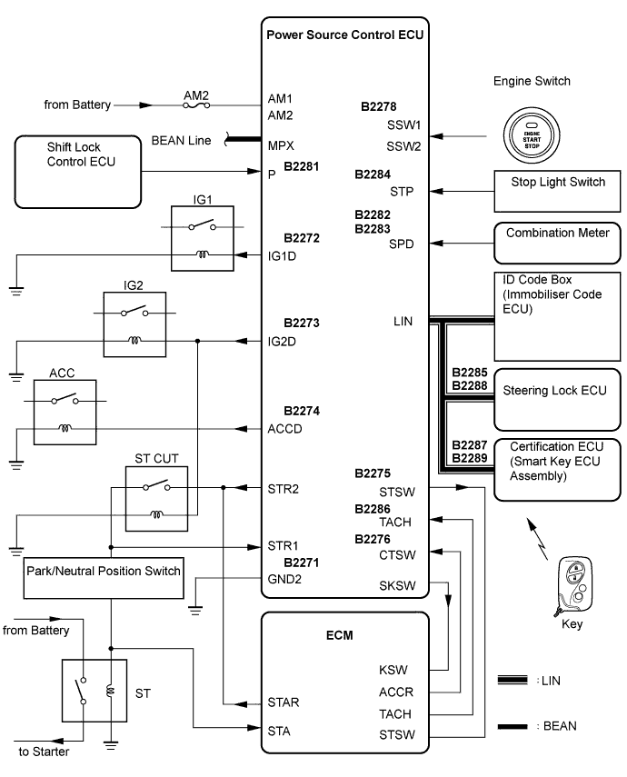
WIRING DIAGRAM
See Cranking Holding Function Circuit Click here.
INSPECTION PROCEDURE
-
EMERGENCY ENGINE START CONTROL
-
If there is a malfunction in the stop light switch or STOP fuse, their signals may not be correctly transmitted to the power source control ECU. This may result in the engine not starting even if the engine switch is pressed while the brake pedal is depressed and the shift lever is in the P position.
To activate the starter:
-
Turn the engine switch from off to on (ACC).
-
Hold pressing and hold the engine switch for 15 seconds.
-
Tech Tips
After the certification ECU (smart key ECU assembly), steering lock ECU, ID code box (immobiliser code ECU) and/or ECM are/is replaced, perform the registration procedures for the engine immobiliser system.
-
PROCEDURE
-
CHECK IF ENGINE START (INITIALIZE STEERING LOCK)
-
Shift lever is in the P.
-
Open and close the driver's door with the engine switch off.
-
Check if the engine can be started.
OK Engine can be started. Tech Tips
After the battery is discharged and then recharged, the engine may not start unless the steering lock is initialized using the above procedure.
NG 
CHECK THE ENGINE SWITCH CONDITION Click here
OK 
END (INITIALIZATION WAS DEFECTIVE)
-
-
CHECK THE ENGINE SWITCH CONDITION
-
Check the power source mode changes.
-
When the key is inside the vehicle and the shift lever is in the P position, check that the power source mode changes.
OK off → on (ACC) → on (IG) → off
-
NG 
GO TO OTHER FLOW CHART (POWER SOURCE MODE DOES NOT CHANGE) Click here
OK 
-
-
CHECK DTC
-
Clear the DTCs Click here.
-
Check for DTCs again.
-
Proceed to the next step based on the inspection result.
Result Result Proceed to No DTC is output A Entry and start system (for start function) DTCs are output B Steering lock system DTCs are output C Engine immobiliser system DTCs are output D Vehicle stability control system DTCs are output E
B
GO TO DIAGNOSTIC TROUBLE CODE CHART (ENTRY AND START SYSTEM) Click here
C
GO TO DIAGNOSTIC TROUBLE CODE CHART (STEERING LOCK SYSTEM) Click here
D
GO TO DIAGNOSTIC TROUBLE CODE CHART (ENGINE IMMOBILISER SYSTEM) Click here
E
GO TO DIAGNOSTIC TROUBLE CODE CHART (VEHICLE STABILITY CONTROL SYSTEM) Click here
A
-
-
CHECK CRANKING FUNCTION
-
Check the engine cranking function.
-
When there is fuel in the fuel tank, the key is inside the vehicle, and the shift lever is in the P position, check that depressing the brake pedal and pressing the engine switch crank the engine.
OK Engine cranks.
-
NG
CHECK STEERING LOCK Click here
OK
-
-
READ VALUE USING INTELLIGENT TESTER (ENGINE START REQUEST)
-
Connect the intelligent tester to the DLC3.
Tech Tips
When using the intelligent tester with the engine switch off, turn on and off any of the door courtesy light switches repeatedly at 1.5 second intervals or less until communication between the tester and vehicle starts.
-
Turn the engine switch on (IG).
Smart key: Tester Display Measurement Item/Range Normal Condition Diagnostic Note Engine Start Request Start request signal response / OK or NG OK: Received
NG: Not received
- OK "OK" (received) and "NG" (not received) appear on the screen.
NG
REGISTER RECOGNITION CODE (ECU CODE) Click here
OK
-
-
REPLACE ID CODE BOX (IMMOBILISER CODE ECU)
-
Replace ID code box (immobiliser code ECU).
NEXT
-
-
KEY REGISTRATION
-
Register the key.
NEXT
-
-
CHECK IF THE ENGINE START
-
Shift lever is in the P.
-
Open and close the driver's door with the engine switch off.
-
Check if the engine can be started.
OK Engine can be started. Tech Tips
After the battery is discharged and then recharged, the engine may not start unless the steering lock is initialized using the above procedure.
NG
GO TO SFI SYSTEM Click here
OK
END (ID CODE BOX (IMMOBILISER CODE ECU DEFECTIVE)
-
-
CHECK STEERING LOCK
-
Check if the steering lock is released when turning the engine switch on (ACC).
OK The steering lock is released.
NG
GO TO STEERING LOCK SYSTEM Click here
OK
-
-
READ VALUE USING INTELLIGENT TESTER (S CODE)
-
Connect the intelligent tester to the DLC3.
Tech Tips
When using the the intelligent tester with the engine switch off, turn on and off any of the door courtesy light switches repeatedly at 1.5 second intervals or less until communication between the tester and vehicle starts.
-
Turn the engine switch on (IG).
Smart key: Tester Display Measurement Item/Range Normal Condition Diagnostic Note S Code Check S code check / OK or NG OK: Normal
NG: Malfunction
- OK "OK" is displayed on the screen.
NG
REGISTER RECOGNITION CODE (ECU CODE) Click here
OK
-
-
READ VALUE USING INTELLIGENT TESTER (L CODE)
-
Connect the intelligent tester to the DLC3.
Tech Tips
When using the intelligent tester with the engine switch off, turn on and off any of the door courtesy light switches repeatedly at 1.5 second intervals or less until communication between the tester and vehicle starts.
-
Turn the engine switch on (IG).
Smart key: Tester Display Measurement Item/Range Normal Condition Diagnostic Note L Code Check L code check / OK or NG OK: Normal
NG: Malfunction
- OK "OK" is displayed on the screen.
NG
KEY REGISTRATION Click here
OK
-
-
READ VALUE USING INTELLIGENT TESTER (STOP LIGHT SWITCH)
-
Connect the intelligent tester to the DLC3.
-
Turn the engine switch on (IG).
-
Check the result when the engine switch is turned on (IG) and the engine is started.
Smart key: Tester Display Measurement Item/Range Normal Condition Diagnostic Note Stop Light Switch1 Stop light switch 1 / ON or OFF OK: Brake pedal depressed
NG: Brake pedal released
- OK OK (brake pedal depressed) and OFF (brake pedal released) appear on the screen.
NG
INSPECT FUSE Click here
OK
-
-
READ VALUE USING INTELLIGENT TESTER (PARK/NEUTRAL POSITION SWITCH)
-
Connect the intelligent tester to the DLC3.
-
Turn the engine switch on (IG).
-
Read the Data List according to the displays on the tester screen.
Power Source Control: Tester Display Measurement Item/Range Normal Condition Diagnostic Note Neutral SW Park/Neutral position switch / ON or OFF ON: Shift position is P or N
OFF: Shift position is not P nor N
- OK "ON" (Shift position is P or N) and "OFF" (Shift position is not P nor N) appear on the screen.
NG
INSPECT STARTER RELAY Click here
OK
-
-
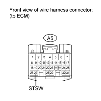
CHECK HARNESS AND CONNECTOR (POWER SOURCE CONTROL ECU - ECM)
-
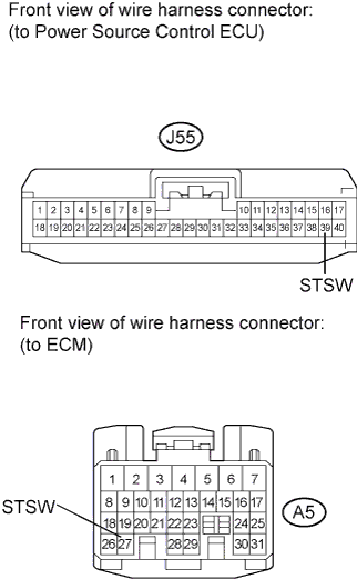
Disconnect the J55 connector from power source control ECU.
-
Disconnect the A5 connector from ECM.
-
Measure the resistance according to the value(s) in the table below.
Standard Resistance Tester Connection Condition Specified Condition J55-39 (STSW) - A5-27 (STSW) Always Below 1Ω J55-39 (STSW) or A5-27 (STSW) Always 10 kΩ or higher
NG
REPAIR OR REPLACE HARNESS OR CONNECTOR (POWER SOURCE CONTROL ECU - ECM)
OK
-
-
CHECK POWER SOURCE CONTROL ECU
-
Reconnect the J55 connector to the power source control ECU.
-
Measure the voltage according to the value(s) in the table below.
Standard Voltage Tester Connection Condition Specified Condition J55-39 (STSW) - Body ground Brake pedal depressed, engine switch hold on (ST) Output voltage at terminals AM1 or AM2 is -2 V or more.
NG
REPLACE POWER SOURCE CONTROL ECU
OK
GO TO SFI SYSTEM
-
-
KEY REGISTRATION
-
Register the key.
NEXT
-
-
CHECK IF ENGINE START
-
Shift lever is in the P position.
-
Open and close the driver's door with the engine switch off.
-
Check if the engine can be started.
OK Engine can be started. Tech Tips
After the battery is discharged and then recharged, the engine may not start unless the steering lock is initialized using the above procedure.
NG
REPLACE STEERING LOCK ACTUATOR Click here
OK
END
-
-
REPLACE STEERING LOCK ACTUATOR
-
Replace the steering lock ECU Click here.
NEXT
-
-
REGISTER RECOGNITION CODE (ECU CODE)
-
Register the recognition code (ECU code).
NEXT
-
-
CHECK IF ENGINE START
-
Shift lever is in the P position.
-
Open and close the driver's door with the engine switch off.
-
Check if the engine can be started.
OK Engine can be started. Tech Tips
After the battery is discharged and then recharged, the engine may not start unless the steering lock is initialized using the above procedure.
NG
REPLACE ID CODE BOX (IMMOBILISER CODE ECU)
OK
END (STEERING LOCK ECU DEFECTIVE)
-
-
REGISTER RECOGNITION CODE (ECU CODE)
-
Register the recognition code (ECU code).
NEXT
-
-
CHECK IF ENGINE START
-
Shift lever is in the P position.
-
Open and close the driver's door with the engine switch off.
-
Check if the engine can be started.
OK Engine can be started. Tech Tips
After the battery is discharged and then recharged, the engine may not start unless the steering lock is initialized using the above procedure.
NG
REPLACE CERTIFICATION ECU (SMART KEY ECU ASSEMBLY) Click here
OK
END
-
-
REPLACE CERTIFICATION ECU (SMART KEY ECU ASSEMBLY)
-
Replace the certification ECU (smart key ECU assembly).
NEXT
-
-
REGISTER RECOGNITION CODE (ECU CODE)
-
Register the recognition code (ECU code).
NEXT
-
-
CHECK IF ENGINE START
-
Shift lever is in the P position.
-
Open and close the driver's door with the engine switch off.
-
Check if the engine can be started.
OK Engine can be started. Tech Tips
After the battery is discharged and then recharged, the engine may not start unless the steering lock is initialized using the above procedure.
NG
REPLACE ID CODE BOX (IMMOBILISER CODE ECU)
OK
END (CERTIFICATION ECU (SMART KEY ECU ASSEMBLY) DEFECTIVE)
-
-
INSPECT FUSE
-
Remove the STOP SW fuse from main body ECU RH (cowl side junction block RH).
-
Measure the resistance according to the value(s) in the table below.
Standard Resistance Tester Connection Condition Specified condition STOP SW fuse Always Below 1Ω
NG
REPLACE STOP SW FUSE
OK
-
-
INSPECT STOP LIGHT SWITCH
-
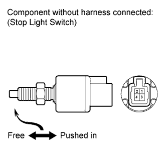
Remove the stop light switch Click here.
-
Measure the resistance according to the value(s) in the table below.
NG
REPLACE STOP LIGHT SWITCH Click here
OK
-
-
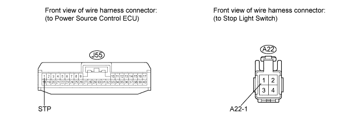
CHECK HARNESS AND CONNECTOR (POWER SOURCE CONTROL ECU - STOP LIGHT SWITCH)
-
Disconnect the J55 connector from the power source control ECU.
-
Measure the resistance according to the value(s) in the table below.
Standard Resistance Tester Connection Condition Specified Condition J55-1 (STP) - A22-1 Always Below 1Ω J55-1 (STP) or A22-1 - Body ground Always 10 kΩ or higher
NG
REPAIR OR REPLACE HARNESS OR CONNECTOR (POWER SOURCE CONTROL ECU - STOP LIGHT SWITCH)
OK
REPLACE POWER SOURCE CONTROL ECU
-
-
INSPECT STARTER RELAY
-
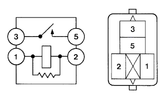
Remove the starter relay from engine room relay block No. 1.
-
Measure the resistance according to the value(s) in the table below.
Standard Resistance Tester Connection Condition Specified Condition 3 - 5 When battery voltage is not applied to terminal 1 and 2 10 kΩ or higher 3 - 5 When battery voltage is applied to terminal 1 and 2 Below 1Ω
NG
REPLACE STARTER RELAY
OK
-
-
INSPECT PARK/NEUTRAL POSITION SWITCH
-
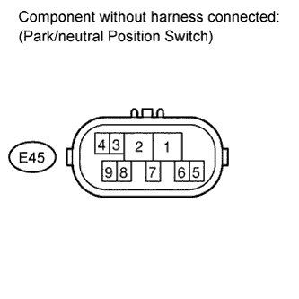
Disconnect the E45 connector from park/neutral position switch.
-
Measure the resistance according to the value(s) in the table below.
Standard Resistance Tester Connection Shift Position Specified Condition 4 - 5 P Below 1Ω 4 - 5 N Below 1Ω 4 - 5 Except N or P 10 kΩ or higher
NG
REPLACE PARK/NEUTRAL POSITION SWITCH
OK
-
-
CHECK HARNESS AND CONNECTOR (POWER SOURCE CONTROL ECU - PARK/NEUTRAL SWITCH)
-
Measure the resistance according to the value(s) in the table below.
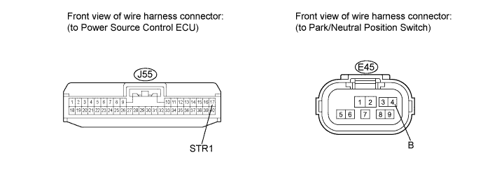
Standard Resistance Tester Connection Condition Specified Condition J55-17 (STR1) - E45-4 (B) Always Below 1Ω J55-17 (STR1) or E45-4 (B) - Body ground Always 10 kΩ or higher
NG
REPAIR OR REPLACE HARNESS OR CONNECTOR (POWER SOURCE CONTROL ECU - PARK/NEUTRAL POSITION SWITCH)
OK
-
-
CHECK HARNESS AND CONNECTOR (PARK/NEUTRAL POSITION SWITCH - STARTER RELAY)
-
Measure the resistance according to the value(s) in the table below.
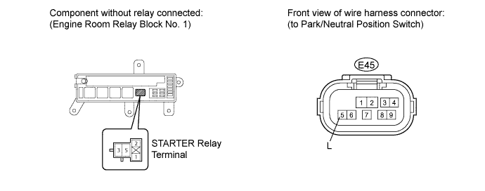
Standard Resistance Tester Connection Condition Specified Condition E45-5 (L) - Engine room relay block No. 1 STARTER relay terminal 1 Always Below 1Ω E45-5 (L) or Engine room relay block No. 1 STARTER relay terminal 1 - Body ground Always 10 kΩ or higher Engine room relay block No. 1 STARTER relay terminal 2 - Body ground Always Below 1Ω
NG
REPAIR OR REPLACE HARNESS OR CONNECTOR
OK
REPLACE POWER SOURCE CONTROL ECU
-