ENTRY AND START SYSTEM (for Start Function), Diagnostic DTC:B2286

| DTC Code | DTC Name |
|---|---|
| B2286 | Runnable Signal Malfunction |
DESCRIPTION
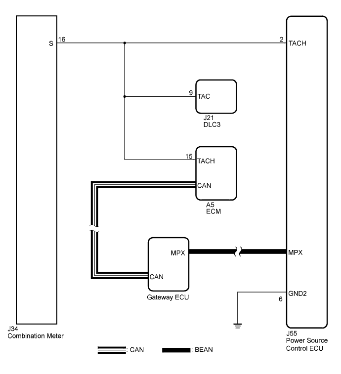
This DTC is output when serial communication signals and multiplex communication signals in the circuit between the power source control ECU and ECM are inconsistent.
Tech Tips
When the power source control ECU is replaced with a new one and the negative (-) battery terminal is connected, the power source mode becomes the IG-ON mode. When the battery is removed and reinstalled, the power source mode that was selected when the battery was removed is restored.
| DTC No. | DTC Detection Condition | Trouble Area |
|---|---|---|
| B2286 | Serial communication signals and multiplex communication signals in the circuit between the power source control ECU and engine control ECU are inconsistent. |
|
WIRING DIAGRAM
INSPECTION PROCEDURE
Tech Tips
Check the connector connection to the terminal to make sure that there is no abnormally such as a loose connection, deformations, etc.
PROCEDURE
-
CHECK MULTIPLEX COMMUNICATION SYSTEM
-
Clear the DTC Click here.
-
Check for the multiplex network communication system DTCs.
Tech Tips
If the DTCs for the multiplex network communication system malfunction are output, inspect those DTCs first.
OK DTC is not output.
NG 
GO TO MULTIPLEX COMMUNICATION SYSTEM Click here
OK 
-
-
CHECK CAN COMMUNICATION SYSTEM
-
Clear the DTC Click here.
-
Check for the CAN communication system DTC.
Tech Tips
If the DTCs for the CAN communication system malfunction are output, inspect those DTCs first.
OK DTC is not output.
NG
GO TO CAN COMMUNICATION SYSTEM Click here
OK
-
-
READ VALUE USING INTELLIGENT TESTER
-
Connect the intelligent tester to the DLC3.
-
Turn the engine switch on (IG).
-
Check the Data List for proper functioning of the engine running.
Power Source Control Tester Display Measurement Item/Range Normal Condition Diagnostic Note Engine Condition Engine condition/STOP or RUN STOP: Engine is stopped
RUN: Engine is running
- OK STOP (engine is stopped) and RUN (engine is running) appear on the screen.
NG 
CHECK HARNESS AND CONNECTOR (POWER SOURCE CONTROL ECU - ECM) Click here
OK
-
-
REPLACE POWER SOURCE CONTROL ECU
-
Replace the power source control ECU.
NEXT
-
-
CHECK FOR DTC
-
Clear the DTC Click here.
-
Check for DTC B2286 is output.
OK DTC B2286 is not output.
NG
REPLACE ECM Click here
OK 
END (POWER SOURCE CONTROL ECU IS DEFECTIVE)
-
-
CHECK HARNESS AND CONNECTOR (POWER SOURCE CONTROL ECU - ECM)
-
Disconnect the J55 connector from power source control ECU.
-
Disconnect the A5 connector from ECM.
-
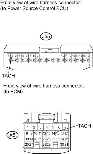
Measure the resistance according to the value(s) in the table below.
Standard Resistance Tester Connection Condition Specified Condition J55-2 (TACH) - A5-15 (TACH) Always Below 1 Ω J55-2 (TACH) or A5-15 (TACH) - Body ground Always 10 kΩ or higher
NG
REPAIR OR REPLACE HARNESS OR CONNECTOR (POWER SOURCE CONTROL ECU - ECM)
OK
-
-
REPLACE POWER SOURCE CONTROL ECU
-
Replace the power source control ECU.
NEXT
-
-
CHECK FOR DTC
-
Clear the DTC.
-
Check for DTC B2286 is output.
OK DTC B2286 is not output.
NG
REPLACE ECM Click here
OK
END (POWER SOURCE CONTROL ECU IS DEFECTIVE)
-