ENGINE IMMOBILISER SYSTEM TERMINALS OF ECU

-
CHECK ENGINE SWITCH
-
Disconnect the J31 engine switch connector.

-
Measure the resistance according to the value(s) in the table below.
Tester Connection Wiring Color Terminal Description Condition Specified Condition J31-8 (AGND) - Body ground GR - Body ground Ground Always Below 1 Ω
-
If the result is not as specified, there may be a malfunction on the wire harness side.
-
-
Reconnect the J31 engine switch connector.
-
Measure the voltage according to the value(s) in the table below.
Tester Connection Wiring Color Terminal Description Condition Specified Condition J31-9 (TXCT) - J31-8 (AGND) L - GR Key code output signal Key is not in cabin Below 1 V J31-9 (TXCT) - J31-8 (AGND) L - GR Key code output signal Key is held close to engine switch* Pulse generation
(See waveform 1)
J31-10 (CODE) - J31-8 (AGND) SB - GR Demodulated signal of key code data Key is not in cabin Below 1 V J31-10 (CODE) - J31-8 (AGND) SB - GR Demodulated signal of key code data Key is held close to engine switch* Pulse generation
(See waveform 2)
J31-14 (VC5) - J31-8 (AGND) R - GR Power supply Key is not in cabin Below 1 V J31-14 (VC5) - J31-8 (AGND) R - GR Power supply Brake pedal is depressed* 4.6 to 5.4 V Tech Tips
*: Remove the key battery before performing this inspection.
-
If the result is not as specified, the engine switch may have a malfunction.
-
-
Inspect using an oscilloscope.
-
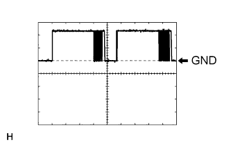
Waveform 1 (Reference)
Item Content Tester Connection J31-9 (TXCT) - J31-8 (AGND) Tool Setting 2 V/DIV., 50 ms./DIV. Condition Key is held close to engine switch* Tech Tips
*: Remove the key battery before performing this inspection.
-
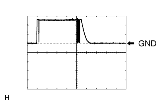
Waveform 2 (Reference)
Item Content Tester Connection J31-10 (CODE) - J31-8 (AGND) Tool Setting 2 V/DIV., 50 ms./DIV. Condition Key is held close to engine switch* Tech Tips
*: Remove the key battery before performing this inspection.
-
-
-
CHECK CERTIFICATION ECU (SMART KEY ECU ASSEMBLY)
-
Disconnect the P33 certification ECU (smart key ECU assembly) connector.

-
Measure the resistance and voltage according to the value(s) in the table below.
Tester Connection Wiring Color Terminal Description Condition Specified Condition P33-1 (+B1) - P33-17 (E) L - W-B +B power supply Always 11 to 14 V P33-17 (E) - Body ground W-B - Body ground Ground Always Below 1 Ω
-
If the result is not as specified, there may be a malfunction on the wire harness side.
-
-
Reconnect the P33 certification ECU (smart key ECU assembly) connector.
-
Measure the resistance and voltage according to the value(s) in the table below.
Tester Connection Wiring Color Terminal Description Condition Specified Condition P33-8 (TXCT) - P33-40 (AGND) G - LG Engine switch TXCT output Key is not in cabin Below 1 V P33-8 (TXCT) - P33-40 (AGND) G - LG Engine switch TXCT output Key is held close to engine switch* Pulse generation (See waveform 1) P33-9 (CODE) - P33-40 (AGND) GR - LG Engine switch CODE input Key is not in cabin Below 1 V P33-9 (CODE) - P33-40 (AGND) GR - LG Engine switch CODE input Key is held close to engine switch* Pulse generation (See waveform 2) P33-18 (IG) - P33-17 (E) B - W-B Ignition power supply Engine switch off Below 1 V P33-18 (IG) - P33-17 (E) B - W-B Ignition power supply Engine switch on (IG) 11 to 14 V P33-19 (ACC) - P33-17 (E) O - W-B ACC power supply Engine switch off Below 1 V P33-19 (ACC) - P33-17 (E) O - W-B ACC power supply Engine switch on (ACC) 11 to 14 V P33-30 (VC5) - P33-40 (AGND) L - LG Engine switch power supply Key is not in cabin Below 1 V P33-30 (VC5) - P33-40 (AGND) L - LG Engine switch power supply Brake pedal is depressed* 4.6 to 5.4 V P33-40 (AGND) - Body ground LG - Body ground Engine switch ground Always Below 1 Ω Tech Tips
*: Remove the key battery before performing this inspection.
-
If the result is not as specified, the certification ECU (smart key ECU assembly) may have a malfunction.
-
-
Inspect using an oscilloscope.
-
Waveform 1 (Reference)
Item Content Tester Connection P33-8 (TXCT) - P33-40 (AGND) Tool Setting 2 V/DIV., 50 ms./DIV. Condition Key is held close to engine switch* Tech Tips
*: Remove the key battery before performing this inspection.
-
Waveform 2 (Reference)
Item Content Tester Connection P33-9 (CODE) - P33-40 (AGND) Tool Setting 2 V/DIV., 50 ms./DIV. Condition Key is held close to engine switch* Tech Tips
*: Remove the key battery before performing this inspection.
-
-
-
CHECK ID CODE BOX (IMMOBILISER CODE ECU)
-
Disconnect the J69 ID code box (immobiliser code ECU) connector.

-
Measure the resistance and voltage according to the value(s) in the table below.
Tester Connection Wiring Color Terminal Description Condition Specified Condition J69-1 (+B) - J69-8 (GND) G - W-B +B power supply Always 11 to 14 V J69-8 (GND) - Body ground W-B - Body ground Ground Always Below 1 Ω
-
If the result is not as specified, there may be a malfunction on the wire harness side.
-
-
Reconnect the J69 ID code box (immobiliser code ECU) connector.
-
Measure the voltage according to the value(s) in the table below.
Tester Connection Wiring Color Terminal Description Condition Specified Condition J69-5 (EFII) - J69-8 (GND) W - W-B ECM input signal Engine switch off Below 1 V J69-5 (EFII) - J69-8 (GND) W - W-B ECM input signal Within 3 seconds after starter operates and initial combustion occurs, or within 3seconds after engine switch first turned on (IG) after battery disconnected and connected. Pulse generation
(See waveform 1)
J69-6 (EFIO) - J69-8 (GND) P - W-B ECM output signal Engine switch off Below 1 V J69-6 (EFIO) - J69-8 (GND) P - W-B ECM output signal Engine switch on (IG) Pulse generation
(See waveform 2)
-
If the result is not as specified, the ID code box (immobiliser code ECU) may have a malfunction.
-
-
Inspect using an oscilloscope.
-
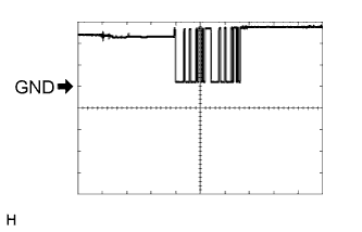
Waveform 1 (Reference)
Item Content Tester Connection J69-5 (EFII) - J69-8 (GND) Tool Setting 5 V/DIV., 500 ms./DIV. Condition Within 3 seconds after starter operates and initial combustion occurs, or within 3seconds after engine switch first turned on (IG) after battery disconnected and connected. -
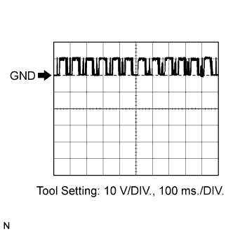
Waveform 2 (Reference)
Item Content Tester Connection J69-6 (EFIO) - J69-8 (GND) Tool Setting 10 V/DIV., 100 ms./DIV. Condition Engine switch on (IG)
-
-
-
CHECK STEERING LOCK ECU (STEERING LOCK ACTUATOR ASSEMBLY)
-
Disconnect the J29 steering lock ECU (steering lock actuator assembly) connector.

-
Measure the resistance and voltage according to the value(s) in the table below.
Tester Connection Wiring Color Terminal Description Condition Specified Condition J29-1 (GND) - Body ground W-B - Body ground Ground Always Below 1 Ω J29-2 (SGND) - Body ground W-B - Body ground Ground Always Below 1 Ω J29-6 (IG2) - Body ground LG - Body ground Ignition power supply Engine switch off Below 1 V J29-6 (IG2) - Body ground LG - Body ground Ignition power supply Engine switch on (IG) 11 to 14 V J29-7 (B) - Body ground O - Body ground +B power supply Always 11 to 14 V
-
If the result is not as specified, there may be a malfunction on the wire harness side.
-
-
-
CHECK POWER SOURCE CONTROL ECU
-
Disconnect the J55 ECU connector.

-
Measure the resistance and voltage according to the value(s) in the table below.
Tester Connection Wiring Color Terminal Description Condition Specified Condition J55-6 (GND2) - Body ground W-B - Body ground Ground Always Below 1 Ω J55-12 (AM2) - Body ground O -Body ground +B power supply Always 11 to 14 V J55-33 (AM1) - Body ground O -Body ground +B power supply Always 11 to 14 V
-
If the result is not as specified, there may be a malfunction on the wire harness side.
-
-
-
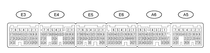
CHECK ECM
-
Disconnect the E6 ECM connector.
-
Measure the resistance according to the value(s) in the table below.
Tester Connection Wiring Color Terminal Description Condition Specified Condition E6-1 (E1) - Body ground W-B - Body ground Ground Always Below 1 Ω If the result is not as specified, there may be a malfunction on the wire harness side.
-
Reconnect the E6 ECM connector.
-
Measure the voltage according to the value(s) in the table below.
Tester Connection Wiring Color Terminal Description Condition Specified Condition A6-30 (IMO) - E6-1 (E1) W-R - W-B ID code box (immobiliser code ECU) output signal Engine switch off Below 1 V A6-30 (IMO) - E6-1 (E1) W-R - W-B ID code box (immobiliser code ECU) output signal Within 3 seconds after starter operates and initial combustion occurs, or within 3seconds after engine switch first turned on (IG) after battery disconnected and connected. Pulse generation
(See waveform 1)
A6-31 (IMI) - E6-1 (E1) LG - W-B ID code box (immobiliser code ECU) input signal Engine switch off Below 1 V A6-31 (IMI) - E6-1 (E1) LG - W-B ID code box (immobiliser code ECU) input signal Engine switch on (IG) Pulse generation
(See waveform 2)
If the result is not as specified, the ECM may have a malfunction.
-
Inspect using an oscilloscope.
-
Waveform 1 (Reference)
Item Content Tester Connection A6-30 (IMO) - E6-1 (E1) Tool Setting 5 V/DIV., 500 ms./DIV. Condition Within 3 seconds after starter operates and initial combustion occurs, or within 3seconds after engine switch first turned on (IG) after battery disconnected and connected. -
Waveform 2 (Reference)
Item Content Tester Connection A6-31 (IMI) - E6-1 (E1) Tool Setting 2 V/DIV., 1 s./DIV. Condition Engine switch on (IG)
-
-
-
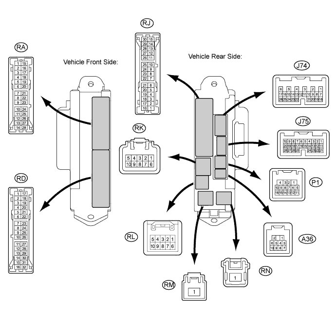
CHECK MAIN BODY ECU RH (COWL SIDE JUNCTION BLOCK RH)
-
Disconnect the RD and RM cowl side junction block RH connectors.
-
Measure the resistance and voltage according to the value(s) in the table below.
Tester Connection Wiring Color Terminal Description Condition Specified Condition RD-7 (GND2) - Body ground W-B - Body ground Ground Always Below 1 Ω RK-5 (BECU) - Body ground G-R - Body ground Battery power supply Always 11 to 14 V RN-1 (BATB) - Body ground R - Body ground Ignition power supply Always 11 to 14 V
-
If the result is not as specified, there may be a malfunction on the wire harness side.
-
-
Reconnect the RD and RM cowl side junction block RH connectors.
-
Measure the voltage according to the value(s) in the table below.
Tester Connection Wiring Color Terminal Description Condition Specified Condition J74-24 (IND) - Body ground LG - Body ground Indicator light signal Key is not in cabin (immobiliser system is not set) Alternating between 11 to 14 V (0.2 seconds) to below 1 V
-
If the result is not as specified, the main body ECU RH (cowl side junction block RH) may have a malfunction.
-
-