ENTRY AND START SYSTEM (for Start Function), Diagnostic DTC:B2276

| DTC Code | DTC Name |
|---|---|
| B2276 | ACCR Signal Circuit Malfunction |
DESCRIPTION
This DTC is output when the ACCR output circuits inside the power source control ECU are open or short.
Tech Tips
When the power source control ECU is replaced with a new one and the negative (-) battery terminal is connected, the power source mode becomes the IG-ON mode. When the battery is removed and reinstalled, the power source mode that was selected when the battery was removed is restored.
| DTC No. | DTC Detection Condition | Trouble Area |
|---|---|---|
| B2276 | ACCR output circuit inside power source control ECU or other related circuit is malfunctioning |
|
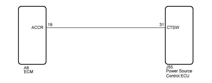
WIRING DIAGRAM
INSPECTION PROCEDURE
PROCEDURE
-
CHECK FOR DTC
-
Clear the DTC Click here.
-
Turn the engine switch on (IG).
-
After 50 seconds have elapsed, check if the trouble occurs again.
OK DTC B2276 is output.
NG 
CHECK HARNESS AND CONNECTOR (POWER SOURCE CONTROL ECU - ECM) Click here
OK 
USE SIMULATION METHOD TO CHECK Click here
-
-
CHECK HARNESS AND CONNECTOR (POWER SOURCE CONTROL ECU - ECM)
-
Disconnect the J55 connector from power source control ECU.
-
Disconnect the A6 connector from ECM.
-
Measure the resistance according to the value(s) in the table below.
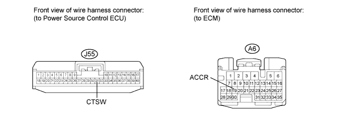
Standard Resistance Tester Connection Condition Specified Condition J55-31 (CTSW) - A6-19 (ACCR) Always Below 1Ω J55-31 (CTSW) or A6-19 (ACCR) - Body ground Always 10 kΩ or higher
NG 
REPAIR OR REPLACE HARNESS OR CONNECTOR (POWER SOURCE CONTROL ECU - ECM)
OK 
-
-
CHECK POWER SOURCE CONTROL ECU
-
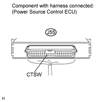
Reconnect the J55 connector to the power source control ECU.
-
Reconnect the A6 connector to the ECM.
-
Measure the voltage according to the value(s) in the table below.
Standard Voltage Tester Connection Condition Specified Condition J55-31 (CTSW) - Body ground Brake pedal depressed, shift lever in P, engine switch is pushed once → on (IG) 0.1 to 0.8 V*1 → output voltage at terminal AM1 or AM" is -2 V or more. Tech Tips
*1: Voltage is output only when the engine is cranking
NG
REPLACE ECM Click here
OK
REPLACE POWER SOURCE CONTROL ECU
-