ENTRY AND START SYSTEM (for Start Function), Diagnostic DTC:B2272

| DTC Code | DTC Name |
|---|---|
| B2272 | Ignition 1 Monitor Malfunction |
DESCRIPTION
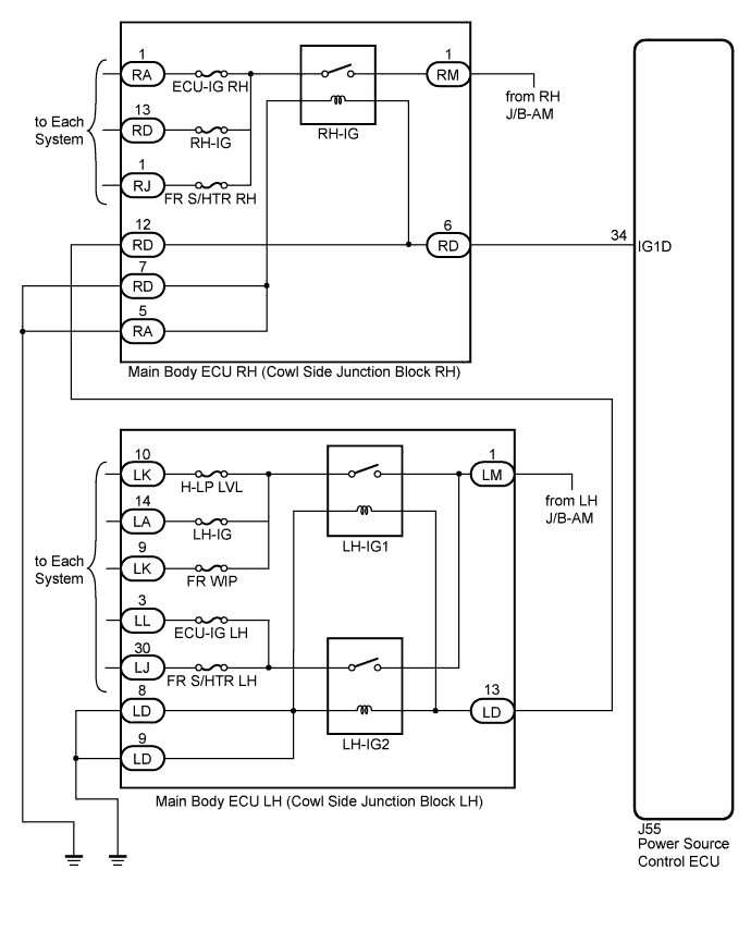
This DTC is output when there is a problem in the IG1 output circuit, which is from the inside of the power source control ECU to the RH-IG or LH-IG relay.
Tech Tips
When the power source control ECU is replaced with a new one and the negative (-) battery terminal is connected, the power source mode becomes the IG-ON mode. When the battery is removed and reinstalled, the power source mode that was selected when the battery was removed is restored.
| DTC No. | DTC Detection Condition | Trouble Area |
|---|---|---|
| B2272 | IG1 relay actuation circuit inside power source control ECU or other related circuit is malfunctioning |
|
WIRING DIAGRAM
INSPECTION PROCEDURE
PROCEDURE
-
READ VALUE USING INTELLIGENT TESTER
-
Connect the intelligent tester to the DLC3.
-
Turn the engine switch on (IG) and turn the intelligent tester main switch on.
-
Select the item below in the Data List, and read the display on the intelligent tester.
Tech Tips
When using the intelligent tester with the engine switch off, turn on and off any of the door courtesy light switches repeatedly at 1.5 second intervals or less until communication between the intelligent tester and vehicle starts.
Power Source Control Tester Display Measurement Item/Range Normal Condition Diagnostic Note IG1 Relay Monitor (Outside) Status of IG1 relay monitor (outer) / ON or OFF ON: Engine switch on (IG) (IG1 relay is ON)
OFF: Engine switch off (IG1 relay is OFF)
- OK "ON" (engine switch on (IG)) appears on the screen.
NG 
CHECK MAIN BODY ECU RH (COWL SIDE JUNCTION BLOCK RH) Click here
OK 
-
-
CHECK FOR DTC
-
Clear the DTCs Click here.
-
Turn the engine switch on (IG).
-
Depress the brake pedal.
-
After 10 seconds have elapsed, check if the trouble occurs again.
-
Check for DTC again.
OK DTC B2282 is not output.
NG 
REPLACE POWER SOURCE CONTROL ECU
OK 
USE SIMULATION METHOD TO CHECK Click here
-
-
CHECK MAIN BODY ECU RH (COWL SIDE JUNCTION BLOCK RH)
-
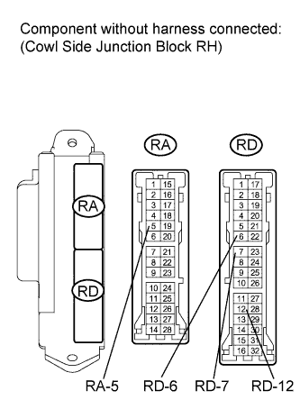
Disconnect the RD and RA connectors.
-
Measure the resistance according to the value(s) in the table below.
Standard Resistance Tester Connection Condition Specified Condition RD-6 - RA-5 or RD-7 Always 68 to 175 Ω RD-6 - RD-12 Always Below 1 Ω RD-6 - Body ground Always 10 kΩ or higher RA-5 or RD-7 - Body ground Always Below 1 Ω
NG
REPLACE MAIN BODY ECU RH (COWL SIDE JUNCTION BLOCK RH)
OK
-
-
CHECK MAIN BODY ECU LH (COWL SIDE JUNCTION BLOCK LH)
-
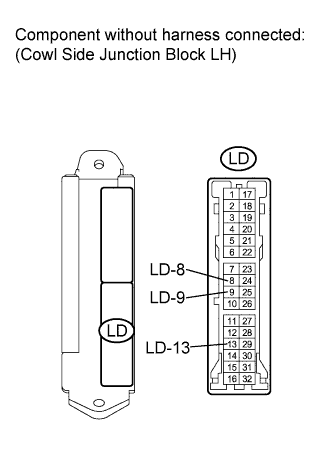
Disconnect the LD connector.
-
Measure the resistance according to the value(s) in the table below.
Standard Resistance Tester Connection Condition Specified Condition LD-13 - LD-8 or LD-9 Always 68 to 250 Ω at 20°C (68°F) LD-13 - Body ground Always 10 kΩ or higher
NG
REPLACE MAIN BODY ECU LH (COWL SIDE JUNCTION BLOCK LH)
OK
-
-
CHECK HARNESS AND CONNECTOR (POWER SOURCE CONTROL ECU - COWL SIDE JUNCTION BLOCK RH)
-
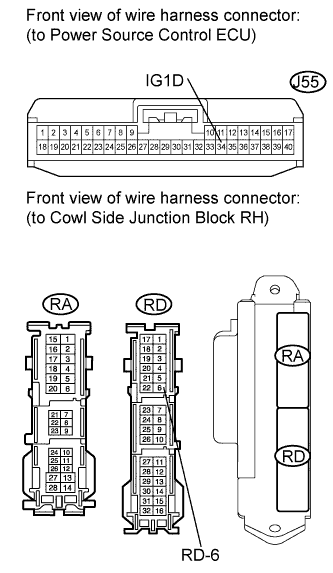
Disconnect the J55 connector.
-
Measure the resistance according to the value(s) in the table below.
Standard Resistance Tester Connection Condition Specified Condition J55-34 (IG1D) - RD-6 Always Below 1 Ω J55-34 (IG1D) or RD-6 - Body ground Always 10 kΩ or higher
NG
REPAIR OR REPLACE HARNESS OR CONNECTOR (POWER SOURCE CONTROL ECU - COWL SIDE JUNCTION BLOCK RH)
OK
-
-
CHECK HARNESS AND CONNECTOR (COWL SIDE JUNCTION BLOCK RH - COWL SIDE JUNCTION BLOCK LH)
-
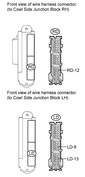
Measure the resistance according to the value(s) in the table below.
Standard Resistance Tester Connection Condition Specified Condition RD-12 - LD-13 Always Below 1 Ω RD-12 or LD-13 - Body ground Always 10 kΩ or higher LD-9 - Body ground Always Below 1 Ω
NG
REPAIR OR REPLACE HARNESS OR CONNECTOR (COWL SIDE JUNCTION BLOCK RH - COWL SIDE JUNCTION BLOCK LH)
OK
REPLACE POWER SOURCE CONTROL ECU
-