ENTRY AND START SYSTEM (for Entry Function) TERMINALS OF ECU

-
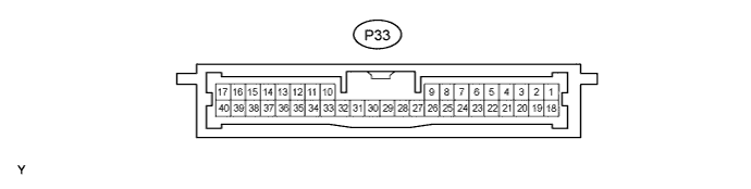
CHECK CERTIFICATION ECU (SMART KEY ECU ASSEMBLY)
-
Disconnect the P33 certification ECU (smart key ECU assembly) connector.
-
Measure the voltage and resistance according to the value(s) in the table below.
Tester Connection Wiring Color Terminal Description Condition Specified Condition P33-1 (+B1) - Body ground L - Body ground +B power supply Always 11 to 14 V P33-17 (E) - Body ground W-B - Body ground Ground Always Below 1 Ω
-
If the result is not as specified, the wire harness side may have a malfunction.
-
-
Reconnect the P33 certification ECU (smart key ECU assembly) connector.
-
Measure the voltage according to the value(s) in the table below.
Tester Connection Wiring Color Terminal Description Condition Specified Condition P33-3 (TSW1) - P33-17 (E)*1 Y - W-B Entry lock switch (driver side) signal Entry lock switch (driver side) not pushed 11 to 14 V P33-3 (TSW1) - P33-17 (E)*1 Y - W-B Entry lock switch (driver side) signal Entry lock switch (driver side) pushed Below 2 V P33-3 (TSW2) - P33-17 (E)*2 BR - W-B Entry lock switch (driver side) signal Entry lock switch (driver side) not pushed 11 to 14 V P33-3 (TSW2) - P33-17 (E)*2 BR - W-B Entry lock switch (driver side) signal Entry lock switch (driver side) pushed Below 2 V P33-4 (TSW2) - P33-17 (E)*1 BR - W-B Entry lock switch (front passenger side) signal Entry lock switch (front passenger side) not pushed 11 to 14 V P33-4 (TSW2) - P33-17 (E)*1 BR - W-B Entry lock switch (front passenger side) signal Entry lock switch (front passenger side) pushed Below 2 V P33-4 (TSW1) - P33-17 (E)*2 Y - W-B Entry lock switch (front passenger side) signal Entry lock switch (front passenger side) not pushed 11 to 14 V P33-4 (TSW1) - P33-17 (E)*2 Y - W-B Entry lock switch (front passenger side) signal Entry lock switch (front passenger side) pushed Below 2 V P33-5 (SEL1) - P33-17 (E)*1 W - W-B Touch sensor activation control signal Move the key more than 5 m (16.4 ft.) away from the front door (driver side) 11 to 14 V P33-5 (SEL1) - P33-17 (E)*1 W - W-B Touch sensor activation control signal Brought to door outside handle assembly Below 1 V P33-5 (SEL2) - P33-17 (E)*2 B - W-B Touch sensor activation control signal Move the key more than 5 m (16.4 ft.) away from the front door (driver side) 11 to 14 V P33-5 (SEL2) - P33-17 (E)*2 B - W-B Touch sensor activation control signal Brought to door outside handle assembly Below 1 V P33-6 (SEL2) - P33-17 (E)*1 B - W-B Touch sensor activation control signal Move the key more than 5 m (16.4 ft) away from the front door (front passenger side) 11 to 14 V P33-6 (SEL2) - P33-17 (E)*1 B - W-B Touch sensor activation control signal Brought to door outside handle assembly Below 1 V P33-6 (SEL1) - P33-17 (E)*2 W - W-B Touch sensor activation control signal Move the key more than 5 m (16.4 ft) away from the front door (front passenger side) 11 to 14 V P33-6 (SEL1) - P33-17 (E)*2 W - W-B Touch sensor activation control signal Brought to door outside handle assembly Below 1 V P33-11 (CLG5) - P33-12 (CG5B) Y - V Indoor electrical key oscillator (front floor) sensor signal 30 seconds after driver side door opened and closed, engine switch off Below 1 V P33-11 (CLG5) - P33-12 (CG5B) Y - V Indoor electrical key oscillator (front floor) sensor signal Within 30 seconds driver side door opened and closed, engine switch off Alternating between 5 V and below 1 V P33-13 (CLG6) - P33-14 (CG6B) LG - O Indoor electrical key oscillator (rear floor) sensor signal 30 seconds after driver side door opened and closed, engine switch off Below 1 V P33-13 (CLG6) - P33-14 (CG6B) LG - O Indoor electrical key oscillator (rear floor) sensor signal Within 30 seconds driver side door opened and closed, engine switch off Alternating between 5 V and below 1 V P33-15 (CLG7) - P33-16 (CG7B) SB - P Indoor electrical key oscillator (luggage compartment) sensor signal Luggage compartment door opener outer switch OFF Below 1 V P33-15 (CLG7) - P33-16 (CG7B) SB - P Indoor electrical key oscillator (luggage compartment) sensor signal Luggage compartment door opener outer switch ON Alternating between 5 V and below 1 V P33-18 (IG) - Body ground B - Body ground Ignition power supply Engine switch off Below 1 V P33-18 (IG) - Body ground B - Body ground Ignition power supply Engine switch on (IG) 11 to 14 V P33-19 (ACC) - Body ground O - Body ground ACC power supply Engine switch off Below 1 V P33-19 (ACC) - Body ground O - Body ground ACC power supply Engine switch on (ACC) 11 to 14 V P33-22 (SEN1) - P33-17 (E)*1 G - W-B Touch sensor detection signal Door outside handle assembly (driver side) touched Below 2 V P33-22 (SEN1) - P33-17 (E)*1 G - W-B Touch sensor detection signal Door outside handle assembly (driver side) not touched 11 to 14 V P33-22 (SEN2) - P33-17 (E)*2 W - W-B Touch sensor detection signal Door outside handle assembly (driver side) touched Below 2 V P33-22 (SEN2) - P33-17 (E)*2 W - W-B Touch sensor detection signal Door outside handle assembly (driver side) not touched 11 to 14 V P33-23 (SEN2) - P33-17 (E)*1 W - W-B Touch sensor detection signal Door outside handle assembly (front passenger side) touched Below 2 V P33-23 (SEN2) - P33-17 (E)*1 W - W-B Touch sensor detection signal Door outside handle assembly (front passenger side) not touched 11 to 14 V P33-23 (SEN1) - P33-17 (E)*2 G - W-B Touch sensor detection signal Door outside handle assembly (front passenger side) touched Below 2 V P33-23 (SEN1) - P33-17 (E)*2 G - W-B Touch sensor detection signal Door outside handle assembly (front passenger side) not touched 11 to 14 V P33-29 (RCO) - P33-17 (E) LG - W-B Entry door control receiver power source Engine switch off, all doors closed and electrical key switch on. 4.5 to 5.5 V P33-29 (RCO) - P33-17 (E) LG - W-B Entry door control receiver power source Engine switch off, all doors closed and electrical key switch off. Below 1 V P33-31 (CLG8) - P33-32 (CG8B) B - W Outside electrical key oscillator (luggage compartment) sensor signal Luggage compartment door opener outer switch OFF Below 1 V P33-31 (CLG8) - P33-32 (CG8B) B - W Outside electrical key oscillator (luggage compartment) sensor signal Luggage compartment door opener outer switch ON Alternating between 5 V and below 1 V P33-33 (CLG1) - P33-34 (CG1B)*1 R - BR Door electrical key oscillator (driver side) sensor signal All doors closed, all doors locked and engine switch off Alternating between 5 V and below 1 V P33-33 (CLG1) - P33-34 (CG1B)*1 R - BR Door electrical key oscillator (driver side) sensor signal Door unlocked or door open Below 1 V P33-33 (CLG2) - P33-34 (CG2B)*2 G - P Door electrical key oscillator (driver side) sensor signal All doors closed, all doors locked and engine switch off Alternating between 5 V and below 1 V P33-33 (CLG2) - P33-34 (CG2B)*2 G - P Door electrical key oscillator (driver side) sensor signal Door unlocked or door open Below 1 V P33-35 (CLG2) - P33-36 (CG2B)*1 G - P Door electrical key oscillator (front passenger side) sensor signal All doors closed, all doors locked and engine switch off Alternating between 5 V and below 1 V P33-35 (CLG2) - P33-36 (CG2B)*1 G - P Door electrical key oscillator (front passenger side) sensor signal Door unlocked or door open Below 1 V P33-35 (CLG1) - P33-36 (CG1B)*2 R - BR Door electrical key oscillator (front passenger side) sensor signal All doors closed, all doors locked and engine switch off Alternating between 5 V and below 1 V P33-35 (CLG1) - P33-36 (CG1B)*2 R - BR Door electrical key oscillator (front passenger side) sensor signal Door unlocked or door open Below 1 V P33-37 (ASEL) - Body ground SB - Body ground Tuner select signal Engine switch off, luggage compartment door opener outer switch is ON. 4.5 to 5.5 V P33-37 (ASEL) - Body ground SB - Body ground Tuner select signal Engine switch off, luggage compartment door opener outer switch is OFF. Below 1 V P33-38 (RDA) - P33-17 (E) R - W-B Entry door control receiver data input signal Engine switch off, all doors closed and electrical key switch off. 11 to 14 V P33-38 (RDA) - P33-17 (E) R - W-B Entry door control receiver data input signal Engine switch off, all doors closed and electrical key switch on. Pulse generation P33-38 (RDA) - Body ground R - Body ground Tuner input signal Engine switch off, all doors closed, the electrical key is not in the detection area. 11 to 14 V P33-38 (RDA) - Body ground R - Body ground Tuner input signal The electrical key is in the detection area. Pulse generation P33-39 (RSSI) - P33-17 (E) Y - W-B Entry door control receiver electric wave existence signal Engine switch off, all doors closed, the electrical key is not in the detection area. 11 to 14 V P33-39 (RSSI) - P33-17 (E) Y - W-B Entry door control receiver electric wave existence signal Engine switch off, all doors closed, the electrical key is in the detection area. Below 1 V
-
*1: for LHD
-
*2: for RHD
If the result is not as specified, the certification ECU (smart key ECU assembly) may have a malfunction.
-
-
-
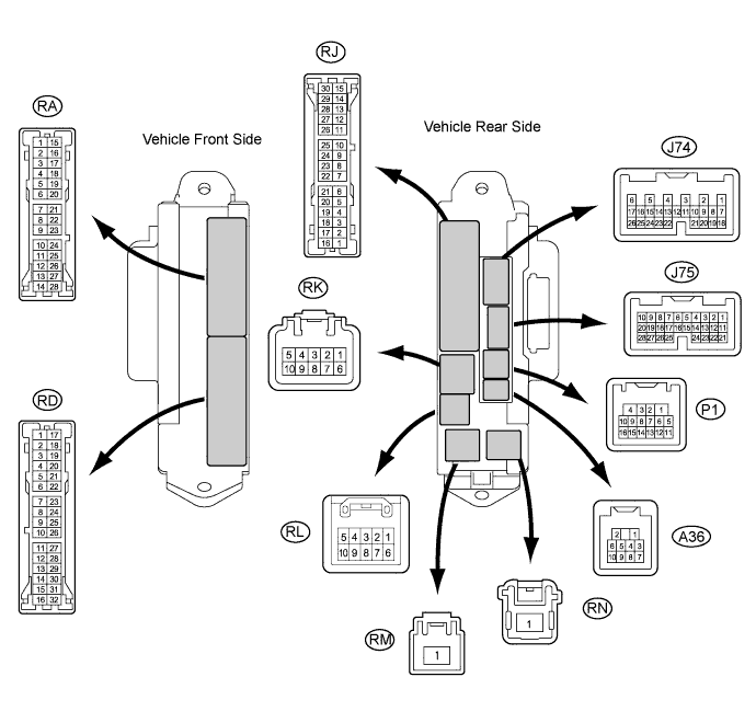
CHECK MAIN BODY ECU RH (COWL SIDE JUNCTION BLOCK RH)
-
Disconnect the RK, RN and RD cowl side junction block RH connectors.
-
Measure the voltage and resistance according to the value(s) in the table below.
Tester Connection Wiring Color Terminal Description Condition Specified Condition RK-5 (BECU) - Body ground G-R - Body ground Battery power supply Always 11 to 14 V RN-1 (BATB) - Body ground R - Body ground Battery power supply Always 11 to 14 V RD-7 (GND2) - Body ground W-B - Body ground Ground Always Below 1 Ω RD-17 (GND1) - Body ground W-B - Body ground Ground Always Below 1 Ω If the result is not as specified, there may be a malfunction in the wire harness side.
-
Reconnect the RK, RN, and RD cowl side junction block RH connectors.
-
Measure the voltage according to the value(s) in the table below.
Tester Connection Wiring Color Terminal Description Condition Specified Condition P1-14 (DCTY) - Body ground W - Body ground Driver side door courtesy switch input Driver side door open Below 1 V P1-14 (DCTY) - Body ground W - Body ground Driver side door courtesy switch input Driver side door closed 11 to 14 V J75-23 (PCTY) - Body ground B - Body ground*1
V - Body ground*2
Front passenger side door courtesy switch input Front passenger side door open Below 1 V J75-23 (PCTY) - Body ground B - Body ground*1
V - Body ground*2
Front passenger side door courtesy switch input Front passenger side door closed 11 to 14 V RA-11 (LCTY) - Body ground BR - Body ground Rear door LH courtesy light switch input Rear door LH open Below 1 V RA-11 (LCTY) - Body ground BR - Body ground Rear door LH courtesy light switch input Rear door LH closed 11 to 14 V P1-16 (RCTY) - Body ground O - Body ground Rear door RH courtesy light switch input Rear door RH open Below 1 V P1-16 (RCTY) - Body ground O - Body ground Rear door RH courtesy light switch input Rear door RH closed 11 to 14 V J75-25 (LGCY) - Body ground L - Body ground Luggage compartment door courtesy light switch input Luggage compartment door open Below 1 V J75-25 (LGCY) - Body ground L - Body ground Luggage compartment door courtesy light switch input Luggage compartment door closed 11 to 14 V
-
*1: for LHD
-
*2: for RHD
If the result is not as specified, the main body ECU RH (cowl side junction block RH) may have a malfunction.
-
-
-
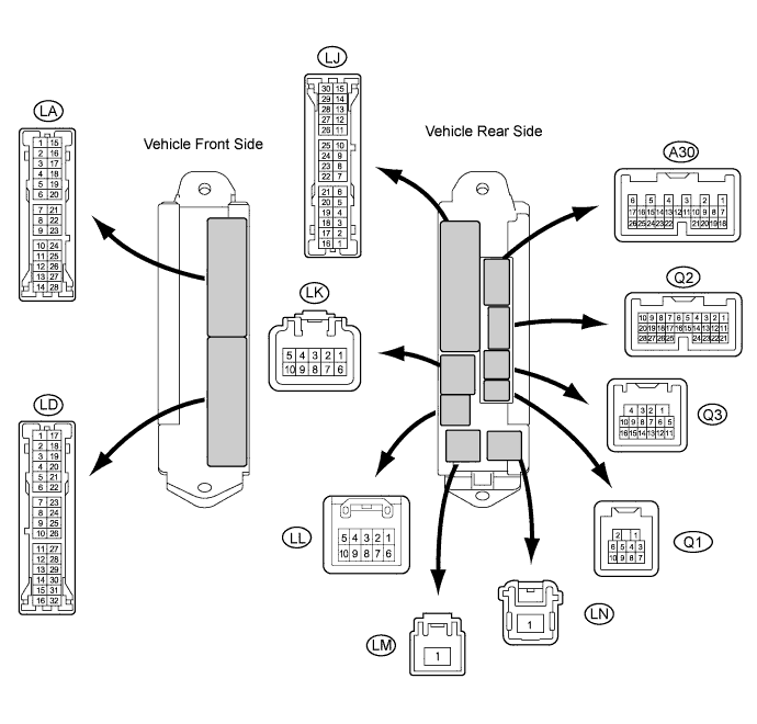
CHECK MAIN BODY ECU LH (COWL SIDE JUNCTION BLOCK LH)
-
Disconnect the LD cowl side junction block LH connector.
-
Measure the voltage and resistance according to the value(s) in the table below.
Tester Connection Wiring Color Terminal Description Condition Specified Condition LD-3 (GND) - Body ground W-B - Body ground Ground Always Below 1 Ω LD-18 (MPXB) - Body ground LG - Body ground Battery power supply Always 11 to 14 V If the result is not as specified, there may be a malfunction in the wire harness side.
-
Reconnect the LD cowl side junction block LH connector.
-
Measure the voltage according to the value(s) in the table below.
Tester Connection Wiring Color Terminal Description Switch Condition Specified Condition Q3-13 (LPSW) - Body ground BR - Body ground Luggage compartment opener outer switch signal Luggage compartment opener outer switch OFF 11 to 14 V Q3-13 (LPSW) - Body ground BR - Body ground Luggage compartment opener outer switch signal Luggage compartment opener outer switch ON Below 1 V If the result is not as specified, the main body ECU LH (cowl side junction block LH) may have a malfunction.
-