ENTRY AND START SYSTEM (for Entry Function) Luggage Compartment Door Entry Unlock Function does not Operate when Key is Outside Luggage Compartment
DESCRIPTION
When the entry luggage compartment open function does not operate, one of the following may be the cause: 1) luggage compartment door opener outer switch malfunction; 2) communication malfunction with the outside electrical key oscillator (luggage compartment); 3) the main body ECU LH (cowl side junction block LH) receives the luggage compartment door opener outer switch ON signal, but is unable to send the signal to the certification ECU (smart key ECU assembly) through BEAN communication; or 5) certification ECU (smart key ECU assembly) malfunction.
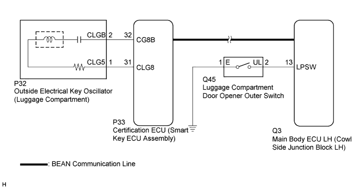
WIRING DIAGRAM
INSPECTION PROCEDURE
PROCEDURE
-
READ VALUE USING INTELLIGENT TESTER (LUGGAGE COMPARTMENT DOOR OPEN MODE)
-
Connect the intelligent tester to the DLC3.
-
Turn the engine switch on (IG).
-
Turn the intelligent tester on.
-
Enter the following menus: Body / Entry & Start / Data List.
-
Read the Data List according to the display on the intelligent tester.
Entry & Start (Certification ECU (Smart Key ECU Assembly)) Tester Display Measurement Item/Range Normal Condition Diagnostic Note Trunk Open Mode Luggage compartment door open mode / ON or OFF Customization status displayed - Result Result Proceed to Entry luggage compartment door open mode is OFF A Entry luggage compartment door open mode is ON B
A 
PERFORM CUSTOMIZE SETTING Click here
B 
-
-
CHECK LUGGAGE COMPARTMENT DOOR OPENER SYSTEM (OPEN OPERATION)
-
When the luggage compartment door opener inner switch is operated, check that the luggage compartment door opens Click here.
OK Luggage compartment door opens.
NG
GO TO LUGGAGE COMPARTMENT DOOR OPENER SYSTEM (Proceed to Luggage Compartment Door Opener does not Operate) Click here
OK
-
-
READ VALUE USING INTELLIGENT TESTER (LUGGAGE COMPARTMENT DOOR OPENER SWITCH)
-
Connect the intelligent tester to the DLC3.
-
Turn the engine switch on (IG).
-
Turn the intelligent tester on.
-
Enter the following menus: Body / Body No. 3 / Data List.
-
Read the Data List according to the display on the intelligent tester.
Body No. 3 (Main Body ECU LH (Cowl Side Junction Block LH)) Tester Display Measurement Item/Range Normal Condition Diagnostic Note Luggage Push Switch Luggage compartment door opener outer switch / ON or OFF ON: Luggage compartment door opener outer switch is pushed
OFF: Luggage compartment door opener outer switch is not pushed
- OK On the intelligent tester screen, the display changes between ON and OFF according to the chart above.
NG 
INSPECT LUGGAGE COMPARTMENT DOOR OPENER OUTER SWITCH Click here
OK
-
-
CHECK WAVE ENVIRONMENT
-
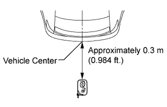
Bring the electrical key transmitter near the outside electrical key oscillator (luggage compartment), and perform an entry luggage compartment open function check.
Note
If the key is brought within 0.2 m (0.656 ft.) of the rear bumper, communication is not possible.
Tech Tips
-
When the electrical key transmitter is brought near the outside electrical key oscillator (luggage compartment), the possibility of wave interference decreases, and it can be determined if wave interference is causing the problem symptom.
-
If the operation check is normal, the possibility of wave interference is high. Also, added vehicle components may cause wave interference. If installed, remove them and perform the operation check.
Result Result Proceed to Operation check is normal A Operation check fails B -
A
AFFECTED BY WAVE INTERFERENCE
B
-
-
PERFORM KEY DIAGNOSTIC MODE INSPECTION
-
Diagnostic mode inspection (outside electrical key oscillator (luggage compartment))
-
Connect the intelligent tester to the DLC3.
-
Turn the engine switch on (IG).
-
Turn the intelligent tester on.
-
Enter the following menus: Body / Entry & Start / Key Communication Check / Overhead + Luggage (outside).
-
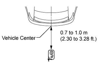
When the electrical key transmitter is held at the same height as the rear bumper upper surface aligning it with the center of the rear of the vehicle, check that the wireless door lock buzzer sounds.
Tech Tips
If the buzzer sounds, it can be determined that the luggage compartment exterior transmitter is operating normally.
OK Wireless door lock buzzer sounds.
-
NG
CHECK HARNESS AND CONNECTOR (CERTIFICATION ECU - OUTSIDE ELECTRICAL KEY OSCILLATOR) Click here
OK 
REPLACE CERTIFICATION ECU (SMART KEY ECU ASSEMBLY)
-
-
CHECK HARNESS AND CONNECTOR (CERTIFICATION ECU - OUTSIDE ELECTRICAL KEY OSCILLATOR)
-
Disconnect the certification ECU (smart key ECU assembly) connector.
-
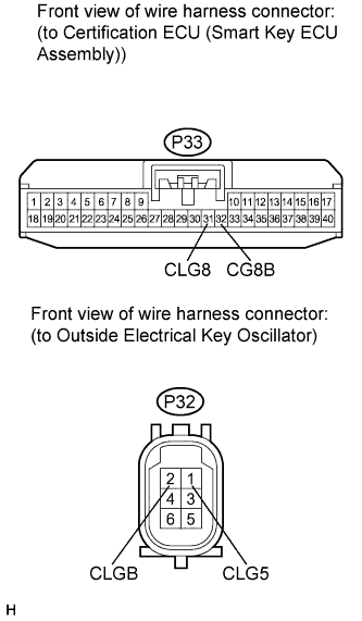
Disconnect the outside electrical key oscillator (luggage compartment) connector.
-
Measure the resistance according to the value(s) in the table below.
Standard Resistance Tester Connection Condition Specified Condition P33-32 (CG8B) - P32-2 (CLGB) Always Below 1 Ω P33-31 (CLG8) - P32-1 (CLG5) Always Below 1 Ω P33-32 (CG8B) - Body ground Always 10 kΩ or higher P33-31 (CLG8) - Body ground Always 10 kΩ or higher
NG
REPAIR OR REPLACE HARNESS OR CONNECTOR
OK
-
-
REPLACE OUTSIDE ELECTRICAL KEY OSCILLATOR (LUGGAGE COMPARTMENT)
-
Replace the outside electrical key oscillator (luggage compartment) Click here.
NEXT
-
-
CHECK OUTSIDE ELECTRICAL KEY OSCILLATOR (OPERATION)
-
Check that the entry functions operate normally Click here.
OK Entry functions operate normally.
NG
REPLACE CERTIFICATION ECU (SMART KEY ECU ASSEMBLY)
OK
END (OUTSIDE ELECTRICAL KEY OSCILLATOR IS DEFECTIVE)
-
-
INSPECT LUGGAGE COMPARTMENT DOOR OPENER OUTER SWITCH
-
Remove the luggage compartment door opener outer switch Click here.
-
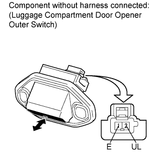
Measure the resistance according to the value(s) in the table below.
Standard Resistance Tester Connection Switch Condition Specified Condition 1 (E) - 2 (UL) Luggage compartment open outer switch not pushed (OFF) 10 kΩ or higher 1 (E) - 2 (UL) Luggage compartment open outer switch pushed (ON) Below 1 Ω
NG
REPLACE LUGGAGE COMPARTMENT DOOR OPENER OUTER SWITCH Click here
OK
-
-
CHECK HARNESS AND CONNECTOR (MAIN BODY ECU LH - OPENER SWITCH)
-
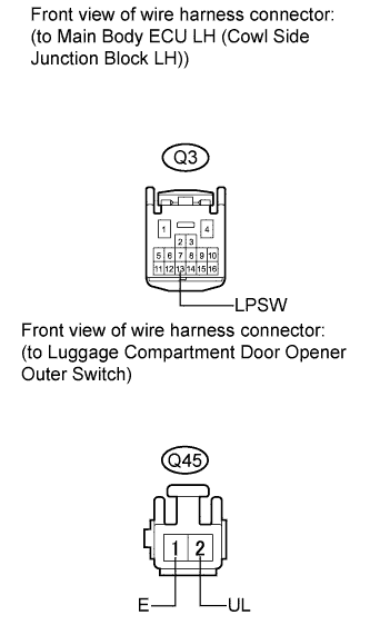
Disconnect the main body ECU LH (cowl side junction block LH) connector.
-
Measure the resistance according to the value(s) in the table below.
Standard Resistance Tester Connection Condition Specified Condition Q3-13 (LPSW) - Q45-2 (UL) Always Below 1 Ω Q45-1 (E) - Body ground Always Below 1 Ω Q3-13 (LPSW) - Body ground Always 10 kΩ or higher
NG
REPAIR OR REPLACE HARNESS OR CONNECTOR
OK
REPLACE MAIN BODY ECU LH (COWL SIDE JUNCTION BLOCK LH)
-