POWER DOOR LOCK CONTROL SYSTEM All Doors LOCK/UNLOCK Functions do not Operate Via Door Control Switch
DESCRIPTION
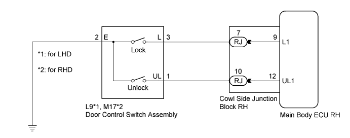
The main body ECU RH (cowl side junction block RH) receives switch signals from the door control switch and activates the door lock motor on each door according to these signals.
WIRING DIAGRAM
INSPECTION PROCEDURE
PROCEDURE
-
READ VALUE USING INTELLIGENT TESTER (DOOR CONTROL SWITCH)
-
Connect the intelligent tester to the DLC3.
-
Turn the engine switch on (IG).
-
Turn the intelligent tester on.
-
Enter the following menus: Body / Body / Data List.
-
Read the Data List according to the display on the intelligent tester.
Body (Main Body ECU RH (Cowl Side Junction Block RH)) Tester Display Measurement Item/Range Normal Condition Diagnostic Note Door Lock SW-Lock Door manual lock switch signal / ON or OFF ON: Front passenger side door control switch on (LOCK)
OFF: Front passenger side door control switch off
- Door Unlock SW-Unlock Door manual unlock switch signal / ON or OFF ON: Front passenger side door control switch on (UNLOCK)
OFF: Front passenger side door control switch off
- OK On the intelligent tester screen, ON or OFF will be displayed accordingly.
NG 
INSPECT DOOR CONTROL SWITCH ASSEMBLY Click here
OK 
REPLACE MAIN BODY ECU RH (COWL SIDE JUNCTION BLOCK RH)
-
-
INSPECT DOOR CONTROL SWITCH ASSEMBLY
-
Remove the door control switch assembly Click here.
-
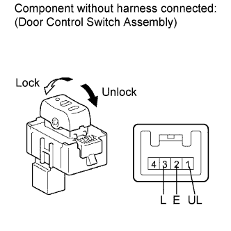
Measure the resistance according to the value(s) in the table below.
Standard Resistance Tester Connection Switch Condition Specified Condition 3 (L) - 2 (E) Lock Below 1 Ω 3 (L) - 2 (E) Off 10 kΩ or higher 1 (UL) - 2 (E) Unlock Below 1 Ω 1 (UL) - 2 (E) Off 10 kΩ or higher
NG 
REPLACE DOOR CONTROL SWITCH ASSEMBLY Click here
OK 
-
-
CHECK HARNESS AND CONNECTOR (DOOR CONTROL SWITCH - MAIN BODY ECU RH AND BODY GROUND)
-
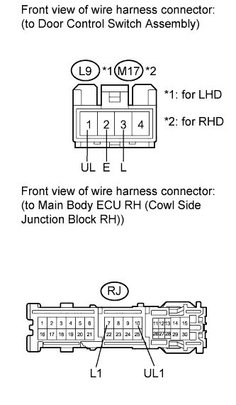
Disconnect the main body ECU RH (cowl side junction block RH) connector.
-
Measure the resistance according to the value(s) in the table below.
Standard Resistance for LHD Tester Connection Condition Specified Condition L9-1 (UL) - RJ-10 (UL1) Always Below 1 Ω L9-3 (L) - RJ-7 (L1) Always Below 1 Ω L9-2 (E) - Body ground Always Below 1 Ω L9-1 (UL) - Body ground Always 10 kΩ or higher L9-3 (L) - Body ground Always 10 kΩ or higher for RHD Tester Connection Condition Specified Condition M17-1 (UL) - RJ-10 (UL1) Always Below 1 Ω M17-3 (L) - RJ-7 (L1) Always Below 1 Ω M17-2 (E) - Body ground Always Below 1 Ω M17-1 (UL) - Body ground Always 10 kΩ or higher M17-3 (L) - Body ground Always 10 kΩ or higher
NG
REPAIR OR REPLACE HARNESS OR CONNECTOR
OK
REPLACE MAIN BODY ECU RH (COWL SIDE JUNCTION BLOCK RH)
-