POWER DOOR LOCK CONTROL SYSTEM All Doors LOCK/UNLOCK Functions do not Operate Via Master Switch, Driver Side Door Key Cylinder
DESCRIPTION
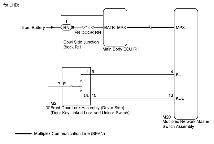
The main body ECU RH (cowl side junction block RH) receives switch signals from the multiplex network master switch, and driver side door key cylinder switch signals from the front door lock (driver side). The main body ECU RH (cowl side junction block RH) activates the door lock motor on each door according to these signals.
WIRING DIAGRAM
INSPECTION PROCEDURE
PROCEDURE
-
CHECK DTC OUTPUT (MULTIPLEX COMMUNICATION SYSTEM)
-
Check for DTC Click here.
OK B1206 output does not reoccur.
NG 
GO TO MULTIPLEX COMMUNICATION SYSTEM (DTC B1206) Click here
OK 
-
-
CHECK FUSE (FR DOOR RH)
-
Remove the FR DOOR RH fuse from the main body ECU RH (cowl side junction block RH).
-
Measure the resistance according to the value(s) in the table below.
Standard Resistance Tester Connection Condition Specified Condition FR DOOR RH fuse Always Below 1 Ω
NG
REPLACE FUSE (FR DOOR RH FUSE)
OK
-
-
CHECK DOOR LOCK OPERATION
-
Check door lock operation Click here.
Result Result Proceed to All doors cannot be locked through driver side door key cylinder A All doors cannot be locked through multiplex network master switch B
A 
READ VALUE USING INTELLIGENT TESTER (DOOR KEY LINKED LOCK AND UNLOCK SWITCH) Click here
B
-
-
REPLACE MULTIPLEX NETWORK MASTER SWITCH ASSEMBLY
-
Replace the multiplex network master switch assembly Click here.
NEXT
-
-
CHECK DOOR LOCK OPERATION
-
Check that all doors can be locked and unlocked by using the multiplex network master switch Click here.
OK All doors can be locked and unlocked with the multiplex network master switch.
NG
REPLACE MAIN BODY ECU RH (COWL SIDE JUNCTION BLOCK RH)
OK 
END (MULTIPLEX NETWORK MASTER SWITCH ASSEMBLY WAS DEFECTIVE)
-
-
READ VALUE USING INTELLIGENT TESTER (DOOR KEY LINKED LOCK AND UNLOCK SWITCH)
-
Connect the intelligent tester to the DLC3.
-
Turn the engine switch on (IG).
-
Turn the intelligent tester on.
-
Enter the following menus: Body / Body / Data List.
-
Read the Data List according to the display on the intelligent tester.
Body (Main Body RH (Cowl Side Junction Block RH)) Tester Display Measurement Item/Range Normal Condition Diagnostic Note Door Key SW-Lock Door key linked lock switch signal / ON or OFF ON: Driver side door key cylinder turned to lock position
OFF: Driver side door key cylinder not turned
- D Door Key SW-UL Door key linked unlock switch signal / ON or OFF ON: Driver side door key cylinder turned to unlock position
OFF: Driver side door key cylinder not turned
- OK On the intelligent tester screen, ON or OFF will be displayed accordingly.
NG
INSPECT FRONT DOOR LOCK ASSEMBLY (DOOR KEY LINKED LOCK AND UNLOCK SWITCH) Click here
OK
REPLACE MAIN BODY ECU RH (COWL SIDE JUNCTION BLOCK RH)
-
-
INSPECT FRONT DOOR LOCK ASSEMBLY (DOOR KEY LINKED LOCK AND UNLOCK SWITCH)
-
Remove the front door lock assembly (driver side) Click here.
-
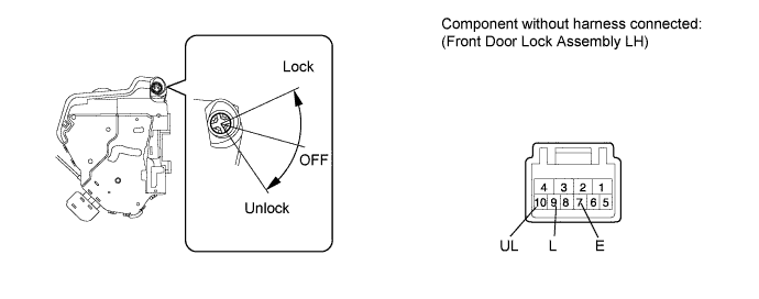
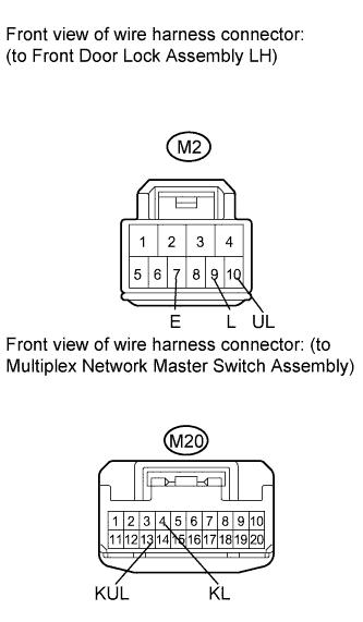
for LHD:
-
Measure the resistance according to the value(s) in the table below.
Standard Resistance Tester Connection Door Lock Condition Specified Condition 9 (L) - 7 (E) Lock Below 1 Ω 9 (L) - 7 (E) OFF 10 kΩ or higher 10 (UL) - 7 (E) Unlock Below 1 Ω 10 (UL) - 7 (E) OFF 10 kΩ or higher
-
-
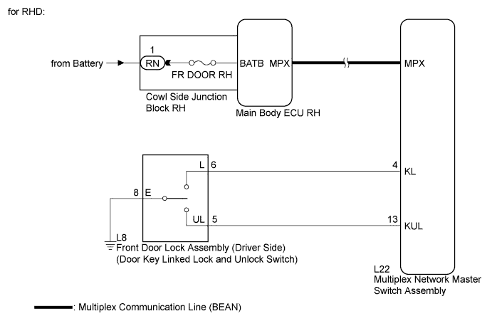
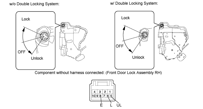
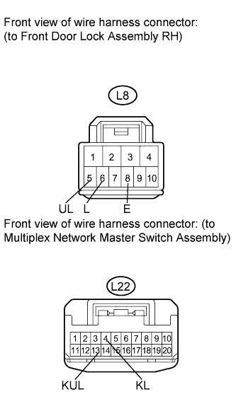
for RHD:
-
Measure the resistance according to the value(s) in the table below.
Standard Resistance Tester Connection Door Lock Condition Specified Condition 6 (L) - 8 (E) Lock Below 1 Ω 6 (L) - 8 (E) OFF 10 kΩ or higher 5 (UL) - 8 (E) Unlock Below 1 Ω 5 (UL) - 8 (E) OFF 10 kΩ or higher
-
NG
REPLACE FRONT DOOR LOCK ASSEMBLY (DRIVER SIDE) Click here
OK
-
-
CHECK HARNESS AND CONNECTOR (FRONT DOOR LOCK - MULTIPLEX NETWORK MASTER SWITCH)
-
for LHD:
-
Disconnect the multiplex network master switch assembly connector.
-
Measure the resistance according to the value(s) in the table below.
Standard Resistance Tester Connection Condition Specified Condition M2-9 (L) - M20-4 (KL) Always Below 1 Ω M2-10 (UL) - M20-13 (KUL) Always Below 1 Ω M2-7 (E) - Body ground Always Below 1 Ω M2-9 (L) - Body ground Always 10 kΩ or higher M2-10 (UL) - Body ground Always 10 kΩ or higher
-
-
for RHD:
-
Disconnect the multiplex network master switch assembly connector.
-
Measure the resistance according to the value(s) in the table below.
Standard Resistance Tester Connection Condition Specified Condition L8-6 (L) - L22-4 (KL) Always Below 1 Ω L8-5 (UL) - L22-13 (KUL) Always Below 1 Ω L8-8 (E) - Body ground Always Below 1 Ω L8-6 (L) - Body ground Always 10 kΩ or higher L8-5 (UL) - Body ground Always 10 kΩ or higher
-
NG
REPAIR OR REPLACE HARNESS OR CONNECTOR
OK
REPLACE MULTIPLEX NETWORK MASTER SWITCH ASSEMBLY Click here
-