POWER DOOR LOCK CONTROL SYSTEM TERMINALS OF ECU

-
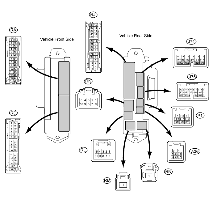
CHECK MAIN BODY ECU RH (COWL SIDE JUNCTION BLOCK RH)
-
Disconnect the RK, RM, RN and RD main body ECU RH (cowl side junction block RH) connectors.
-
Measure the voltage and resistance according to the value(s) in the table below.
Tester Connection Wiring Color Terminal Description Condition Specified Condition RK-5 (BECU) - Body ground G-R - Body ground Battery power supply Always 11 to 14 V RN-1 (BATB) - Body ground R - Body ground Battery power supply Always 11 to 14 V RD-7 (GND2) - Body ground W-B - Body ground Ground Always Below 1 Ω RD-17 (GND1) - Body ground W-B - Body ground Ground Always Below 1 Ω If the result is not as specified, there may be a malfunction in the wire harness.
-
Reconnect the RK, RM, RN and RD main body ECU RH (cowl side junction block RH) connectors.
-
Measure the voltage according to the value(s) in the table below.
Tester Connection Wiring Color Terminal Description Condition Specified Condition P1-14 (DCTY) - Body ground W - Body ground Driver side door courtesy switch input Driver side door open Below 1 V P1-14 (DCTY) - Body ground W - Body ground Driver side door courtesy switch input Engine switch off, and driver side door courtesy switch off 11 to 14 V J75-23 (PCTY) - Body ground B - Body ground*1
V - Body ground*2
Front passenger side door courtesy switch input Front passenger side door open Below 1 V J75-23 (PCTY) - Body ground B - Body ground*1
V - Body ground*2
Front passenger side door courtesy switch input Engine switch off, and passenger side door courtesy switch off 11 to 14 V RA-11 (LCTY) - Body ground BR - Body ground Rear door LH courtesy light switch input Rear door LH open Below 1 V RA-11 (LCTY) - Body ground BR - Body ground Rear door LH courtesy light switch input Engine switch off, and rear door courtesy switch LH off 11 to 14 V P1-16 (RCTY) - Body ground BE - Body ground Rear door RH courtesy light switch input Rear door RH open Below 1 V P1-16 (RCTY) - Body ground BE - Body ground Rear door RH courtesy light switch input Engine switch off, and rear door courtesy switch RH off 11 to 14 V J75-25 (LGCY) - Body ground L - Body ground Luggage compartment door courtesy light switch input Luggage compartment door open Below 1 V J75-25 (LGCY) - Body ground L - Body ground Luggage compartment door courtesy light switch input Engine switch off, and luggage compartment door closed 11 to 14 V RJ-9 (ACT+) - Body ground L - Body ground Door lock motor lock drive output (all doors) Multiplex network master switch (door control switch) or driver side door key cylinder off Below 1 V RJ-9 (ACT+) - Body ground L - Body ground Door lock motor lock drive output (all doors) Multiplex network master switch (door control switch) or driver side door key cylinder lock 11 to 14 V P1-4 (ACTD) - Body ground L - Body ground*1
LG - Body ground*2
Driver side door lock motor unlock drive output Multiplex network master switch (door control switch) or driver side door key cylinder off Below 1 V P1-4 (ACTD) - Body ground L - Body ground*1
LG - Body ground*2
Driver side door lock motor unlock drive output Multiplex network master switch (door control switch) or driver side door key cylinder unlock 11 to 14 V RJ-17 (ACT-) - Body ground LG - Body ground Door lock motor unlock drive output (except driver side) Multiplex network master switch (door control switch) or driver side door key cylinder off Below 1 V RJ-17 (ACT-) - Body ground LG - Body ground Door lock motor unlock drive output (except driver side) Multiplex network master switch (door control switch) or driver side door key cylinder unlock 11 to 14 V J75-27 (LSWP) - Body ground W - Body ground Passenger side door lock position switch input Passenger side door unlock Below 1 V J75-27 (LSWP) - Body ground W - Body ground Passenger side door lock position switch input Engine switch off, all doors closed and passenger side door lock 11 to 14 V RA-2 (LSWL) - Body ground R - Body ground Rear door LH lock position switch input Rear door LH unlock Below 1 V RA-2 (LSWL) - Body ground R - Body ground Rear door LH lock position switch input Engine switch off, all doors closed and rear door LH lock 11 to 14 V J75-5 (LSWR) - Body ground V - Body ground Rear door RH lock position switch input Rear door RH unlock Below 1 V J75-5 (LSWR) - Body ground V - Body ground Rear door RH lock position switch input Engine switch off, all doors closed and rear door RH lock 11 to 14 V RA-7 (GSW) - Body ground L - Body ground Center airbag sensor signal Turning the engine switch on (IG) with the center airbag sensor assembly connector disconnected 4.5 to 5.5 V
-
*1: for LHD
-
*2: for RHD
If the result is not as specified, the main body ECU RH (cowl side junction block RH) may have a malfunction.
-
-
-
CHECK MULTIPLEX NETWORK MASTER SWITCH ASSEMBLY
-
Disconnect the M20*1 or L22*2 multiplex network master switch assembly connector.
-
*1: for LHD
-
*2: for RHD

-
-
Measure the voltage and resistance according to the value(s) in the table below.
for LHD Tester Connection Wiring Color Terminal Description Condition Specified Condition M20-15 (CPUB) - M20-12 (E) G - W-B Battery power supply Always 11 to 14 V M20-18 (SIG) - M20-12 (E) B - W-B SIG power supply Engine switch on (IG) → off 11 to 14 V →
Below 1 V
M20-12 (E) - Body ground W-B - Body ground Ground Always Below 1 Ω M20-4 (KL) - M20-12 (E) L - W-B Door key-linked door lock input Using key, operate driver door lock cylinder from free → lock 10 kΩ or higher →
Below 1 Ω
M20-13 (KUL) - M20-12 (E) W - W-B Door key-linked door unlock input Using key, operate driver door lock cylinder from free → unlock 10 kΩ or higher →
Below 1 Ω
M20-1 (LSW) - M20-12 (E) SB - W-B Driver side door lock position switch input Driver side door unlock → lock Below 1 Ω →
10 kΩ or higher
for RHD Tester Connection Wiring Color Terminal Description Condition Specified Condition L22-15 (CPUB) - L22-12 (E) G - W-B Battery power supply Always 11 to 14 V L22-18 (SIG) - L22-12 (E) B - W-B SIG power supply Engine switch on (IG) → off 11 to 14 V →
Below 1 V
L22-12 (E) - Body ground W-B - Body ground Ground Always Below 1 Ω L22-4 (KL) - L22-12 (E) L - W-B Door key-linked door lock input Using key, operate driver door lock cylinder from free → lock 10 kΩ or higher →
Below 1 Ω
L22-13 (KUL) - L22-12 (E) W - W-B Door key-linked door unlock input Using key, operate driver door lock cylinder from free → unlock 10 kΩ or higher →
Below 1 Ω
L22-1 (LSW) - L22-12 (E) SB - W-B Driver side door lock position switch input Driver side door unlock → lock Below 1 Ω →
10 kΩ or higher
If the result is not as specified, there may be a malfunction on the wire harness side.
-
-
CHECK DOUBLE LOCK DOOR CONTROL RELAY (w/ DOUBLE LOCKING SYSTEM)
-
Disconnect the P34 double lock door control relay connector.

-
Measure the voltage and resistance according to the value(s) in the table below.
Tester Connection Wiring Color Terminal Description Condition Specified Condition P34-1 (+B) - Body ground R - Body ground Battery power supply Always 11 to 14 V P34-7 (CPUB) - Body ground LG - Body ground Battery power supply Always 11 to 14 V P34-14 (GND) - Body ground W-B - Body ground Ground Always Below 1 Ω If the result is not as specified, there may be a malfunction on the wire harness side.
-
Reconnect the P34 double lock door control relay connector.
-
Measure the voltage according to the value(s) in the table below.
Tester Connection Wiring Color Terminal Description Condition Specified Condition P34-5 (DLPD) - Body ground R-B - Body ground Front RH double lock position switch input Double lock UNSET 5 V or higher P34-5 (DLPD) - Body ground R-B - Body ground Front RH double lock position switch input Double lock SET Below 1 V P34-6 (DLPP) - Body ground GR - Body ground Front LH double lock position switch input Double lock UNSET 5 V or higher P34-6 (DLPP) - Body ground GR - Body ground Front LH double lock position switch input Double lock SET Below 1 V P34-11 (DLPR) - Body ground L - Body ground Rear RH double lock position switch input Double lock UNSET 5 V or higher P34-11 (DLPR) - Body ground L - Body ground Rear RH double lock position switch input Double lock SET Below 1 V P34-12 (DLPL) - Body ground Y - Body ground Rear LH double lock position switch input Double lock UNSET 5 V or higher P34-12 (DLPL) - Body ground Y - Body ground Rear LH double lock position switch input Double lock UNSET Below 1 V P34-3 (ACTS) - Body ground V - Body ground All door double lock motor set on output Double lock UNSET Below 1 V P34-3 (ACTS) - Body ground V - Body ground All door double lock motor set on output Double lock SET 11 to 14 V P34-4 (ACTR) - Body ground P - Body ground All door double lock motor set off output Double lock SET Below 1 V P34-4 (ACTR) - Body ground P - Body ground All door double lock motor set off output Double lock UNSET 11 to 14 V If the result is not as specified, the double lock door control relay may have a malfunction.
-