WIRELESS DOOR LOCK CONTROL SYSTEM No Answer-Back (Hazard Warning Light and Wireless Door Lock Buzzer)
DESCRIPTION
If there is no answer-back of the hazard warning light signal and the wireless door lock buzzer although the wireless control function is operating normally, there might be a malfunction in the hazard warning light signal and the wireless door lock buzzer signal which are output from the main body ECU RH (cowl side junction block RH).
Note
Troubleshooting should be started after confirming that the wireless buzzer and hazard answer back function has been switched ON through customization.
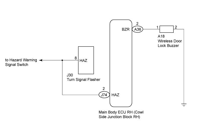
WIRING DIAGRAM
INSPECTION PROCEDURE
PROCEDURE
-
CHECK WIRELESS DOOR LOCK CONTROL SYSTEM
-
Check whether the wireless door lock functions by operating the transmitter switch Click here.
Tech Tips
When the wireless door LOCK/UNLOCK operation can be performed, it means that the wireless signal from the transmitter is properly input to the main body ECU RH (cowl side junction block RH).
Result Result Proceed to Answer-back functions do not operate A Wireless door lock functions do not operate B
B 
GO TO ENTRY AND START SYSTEM Click here
A 
-
-
READ VALUE USING INTELLIGENT TESTER
-
Connect the intelligent tester to the DLC3.
-
Turn the engine switch on (IG).
-
Turn the intelligent tester on.
-
Enter the following menus: Body / Body or Master Switch / Data List.
-
Read the Data List according to the display on the intelligent tester.
Body (Main Body ECU RH (Cowl Side Junction Block RH)) Tester Display Measurement Item/Range Normal Condition Diagnostic Note Passenger Lock Pos SW Front passenger side door lock position switch signal/ON or OFF ON: Front passenger side door is unlocked
OFF: Front passenger side door is locked
- Rear Lock Position SW Rear door lock position switch signal/ON or OFF ON: Rear door is unlocked
OFF: Rear door is locked
- Master Switch (Multiplex Network Master Switch Assembly) Tester Display Measurement Item/Range Normal Condition Diagnostic Note Lock Pos SW Driver side door unlock detection switch signal/ON or OFF ON: Driver side door is unlocked
OFF: Driver side door is locked
- OK On the intelligent tester screen, ON or OFF will be displayed accordingly. Result Result Proceed to OK A NG (for Driver Side) B
(Refer to "Driver Door LOCK/UNLOCK Functions do not Operate" in the problem symptoms table)
NG (for Front Passenger Side) C
(Refer to "Front Passenger Door LOCK/UNLOCK Functions do not Operate" in the problem symptoms table)
NG (for Rear LH Side) D
(Refer to "Rear Door LH LOCK/UNLOCK Functions do not Operate" in the problem symptoms table)
NG (for Rear RH Side) E
(Refer to "Rear Door RH LOCK/UNLOCK Functions do not Operate" in the problem symptoms table)
B
GO TO POWER DOOR LOCK CONTROL SYSTEM (Proceed to Problem Symptoms Table) Click here
C
GO TO POWER DOOR LOCK CONTROL SYSTEM (Proceed to Problem Symptoms Table) Click here
D
GO TO POWER DOOR LOCK CONTROL SYSTEM (Proceed to Problem Symptoms Table) Click here
E
GO TO POWER DOOR LOCK CONTROL SYSTEM (Proceed to Problem Symptoms Table) Click here
A
-
-
PERFORM ACTIVE TEST USING INTELLIGENT TESTER
-
Enter the following menus: Body / Body / Active Test.
-
Perform the Active Test according to the display on the intelligent tester.
Body Tester Display Test Part Control Range Diagnostic Note Hazard Turn signal flasher relay ON/OFF Observe headlights and rear combination lights for correct operation Wireless Buzzer Wireless door lock buzzer ON/OFF - Result Result Proceed to Hazard warning lights do not flash correctly A Wireless door lock buzzer does not sound correctly B Wireless door lock buzzer and hazard warning lights work correctly C
B 
INSPECT WIRELESS DOOR LOCK BUZZER Click here
C
REPLACE MAIN BODY ECU RH (COWL SIDE JUNCTION BLOCK RH)
A
-
-
CHECK HAZARD WARNING LIGHTS
-
Check that the hazard warning lights flash when the hazard warning signal switch is pressed.
OK Hazard warning lights flash continuously.
NG
GO TO LIGHTING SYSTEM Click here
OK
-
-
CHECK HARNESS AND CONNECTOR (TURN SIGNAL FLASHER - MAIN BODY ECU RH)
-
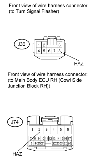
Disconnect the J30 turn signal flasher connector and J74 Main Body ECU RH connector.
-
Measure the resistance according to the value(s) in the table below.
Standard Resistance Tester Connection Condition Specified Condition J30-8 (HAZ) - J74-2 (HAZ) Always Below 1 Ω
NG
REPAIR OR REPLACE HARNESS OR CONNECTOR
OK 
REPLACE MAIN BODY ECU RH (COWL SIDE JUNCTION BLOCK RH)
-
-
INSPECT WIRELESS DOOR LOCK BUZZER
-
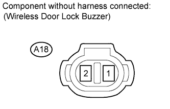
Check the buzzer resistance.
-
Disconnect the A18 buzzer connector.
-
Measure the resistance according to the value(s) in the table below.
Standard Resistance Tester Connection Condition Specified Condition 1 - 2 Always 950 to 1050 Ω Note
When battery voltage is directly applied to the buzzer, the buzzer does not sound.
-
NG
REPLACE WIRELESS DOOR LOCK BUZZER Click here
OK
-
-
CHECK HARNESS AND CONNECTOR (WIRELESS DOOR LOCK BUZZER - MAIN BODY ECU RH)
-
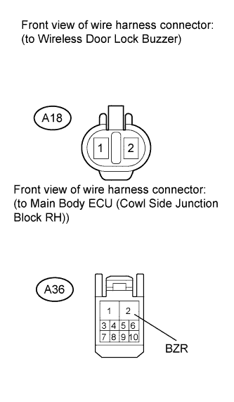
Disconnect the A18 buzzer connector and A36 ECU connector.
-
Measure the resistance according to the value(s) in the table below.
Standard Resistance Tester Connection Condition Specified Condition A36-2 (BZR) - Body ground Always 10 kΩ or higher A18-1 - A36-2 (BZR) Always Below 1 Ω A18-2 - Body ground Always Below 1 Ω
NG
REPAIR OR REPLACE HARNESS OR CONNECTOR
OK
REPLACE MAIN BODY ECU RH (COWL SIDE JUNCTION BLOCK RH)
-