NETWORK GATEWAY ECU REMOVAL

Note
When disassembling the network gateway ECU, eliminate static electricity by touching the vehicle body to prevent the components from being damaged.
-
DISCONNECT CABLE FROM NEGATIVE BATTERY TERMINAL
CAUTION:
Wait for 90 seconds after disconnecting the cable to prevent airbag deployment Click here.
Note
When disconnecting the cable, some systems need to be initialized after the cable is reconnected Click here.
-
REMOVE FRONT DOOR SCUFF PLATE
Tech Tips
Removal procedure of the RH side is the same as that of the LH side Click here.
-
REMOVE FRONT DOOR OPENING TRIM COVER
Tech Tips
Removal procedure of the RH side is the same as that of the LH side Click here.
-
REMOVE SIDE INSTRUMENT PANEL
-
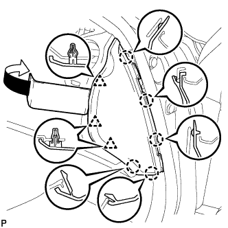
Using a moulding remover, disengage the 5 claws and 3 clips, and then remove the side instrument panel RH.
-
-
REMOVE NO. 2 INSTRUMENT PANEL UNDER COVER SUB-ASSEMBLY (for LHD)
-
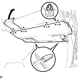
Using a moulding remover, disengage the 4 clips and remove the No. 2 instrument panel under cover sub-assembly.
-
-
REMOVE FRONT PASSENGER SIDE KNEE AIRBAG ASSEMBLY (for LHD)
-
Check that the engine switch is off.
-
Check that the cable is disconnected from the negative (-) battery terminal.
CAUTION:
Wait at least 90 seconds after disconnecting the cable from the negative (-) battery terminal to disable the SRS system.
-
Remove the 3 bolts.
-
Disengage the claw and separate the front passenger side knee airbag assembly.
-
Disconnect the connector and remove the front passenger side knee airbag assembly.
Note
When disconnecting the airbag connector, take care not to damage the airbag wire harness.
-
-
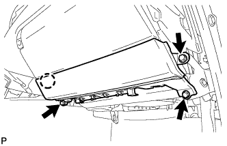
REMOVE GLOVE COMPARTMENT DOOR ASSEMBLY (for LHD)
-
Remove the 5 screws <D>.
-
Disengage the 2 claws.
-
Disconnect the connectors and remove the glove compartment door assembly.
-
-
REMOVE NO. 1 INSTRUMENT PANEL UNDER COVER SUB-ASSEMBLY (for RHD)
-
Remove the 2 screws <D>.
-
Push the 2 claws in the direction indicated by the arrow to disengage them.
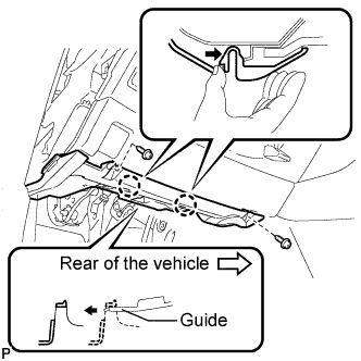
-
Remove the No. 1 instrument panel under cover sub-assembly from the guide as shown in the illustration and pull the cover toward the rear of the vehicle.
-
Disconnect the connectors and remove the No. 1 instrument panel under cover sub-assembly.
-
-
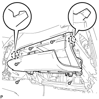
REMOVE LOWER INSTRUMENT PANEL FINISH PANEL SUB-ASSEMBLY (for RHD)
-
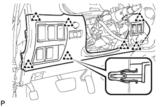
Disengage the 7 clips.
-
Disconnect the connectors and remove the lower instrument panel finish panel sub-assembly.
-
-
REMOVE NETWORK GATEWAY ECU
-
Disconnect the connector.
-
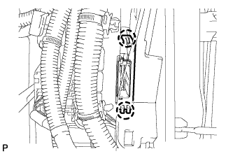
Disengage the 2 claws and remove the cover.
-
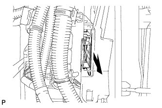
Remove the network gateway ECU.
-