CAN COMMUNICATION SYSTEM Parking Assist ECU Communication Stop Mode
DESCRIPTION
| Detection Item | Symptom | Trouble Area |
|---|---|---|
| Parking Assist ECU Communication Stop Mode |
|
|
Tech Tips
"Parking Assist Monitor" refers to the circuit that includes the parking assist ECU.
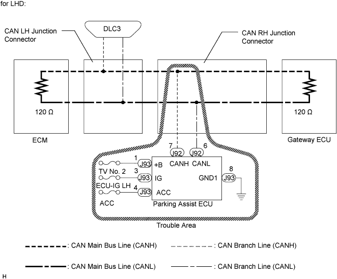
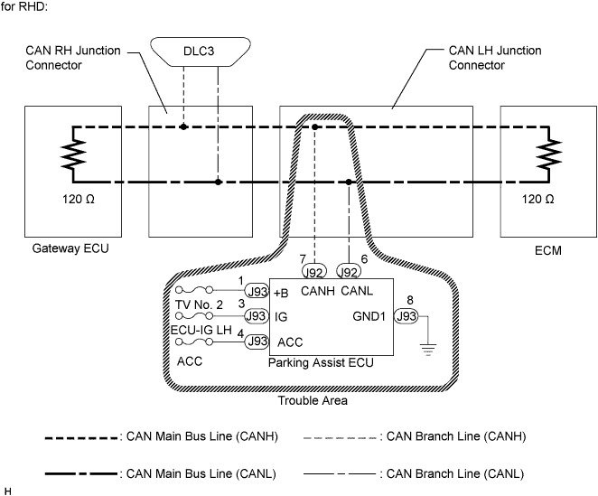
WIRING DIAGRAM
INSPECTION PROCEDURE
Note
-
Turn the engine switch off before measuring the resistance of CAN bus main wires and CAN bus branch wires.
-
After the engine switch is turned off, check that the key reminder warning system and light reminder warning system are not operating.
-
Before measuring the resistance, leave the vehicle as is for at least 1 minute and do not operate the engine switch, any other switches, or the doors. If any doors need to be opened in order to check connectors, open the doors and leave them open.
Tech Tips
Operating the engine switch, any switches, or any doors triggers related ECU and sensor communication with the CAN. This communication will cause the resistance value to change.
PROCEDURE
-
CHECK OPEN IN CAN BUS WIRE (PARKING ASSIST ECU BRANCH LINE)
-
Turn the engine switch off.
-
Disconnect the parking assist ECU connector (J92).
-
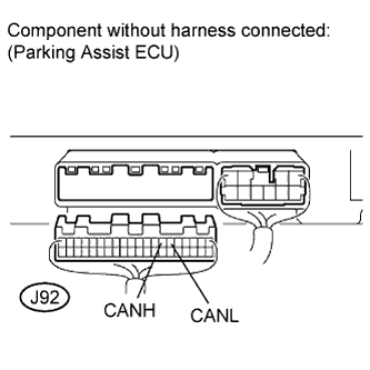
Measure the resistance according to the value(s) in the table below.
Standard Resistance Tester Connection Switch Condition Specified Value J92-7 (CANH) - J92-6 (CANL) Engine switch off 54 to 69 Ω
NG 
REPAIR PARKING ASSIST ECU BRANCH WIRE OR CONNECTOR (CANH, CANL)
OK 
-
-
CHECK WIRE HARNESS (+B, IG, ACC, GND1)
-
Reconnect the parking assist ECU connector (J92).
-
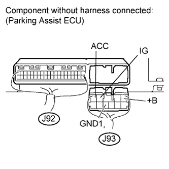
Disconnect the parking assist ECU connector (J93).
-
Measure the resistance according to the value(s) in the table below.
Standard Resistance Tester Connection Condition Specified Value J93-8 (GND1) - Body ground Always Below 1 Ω -
Measure the voltage according to the value(s) in the table below.
Standard Voltage Tester Connection Condition Specified Value J93-1 (+B) - Body ground Always 10 to 14 V J93-3 (IG) - Body ground Engine switch on (IG) 10 to 14 V J93-4 (ACC) - Body ground Engine switch on (ACC) 10 to 14 V
NG
REPAIR OR REPLACE HARNESS OR CONNECTOR
OK 
REPLACE PARKING ASSIST ECU Click here
-