CAN COMMUNICATION SYSTEM Open in CAN Main Bus Line (LHD Models)
DESCRIPTION
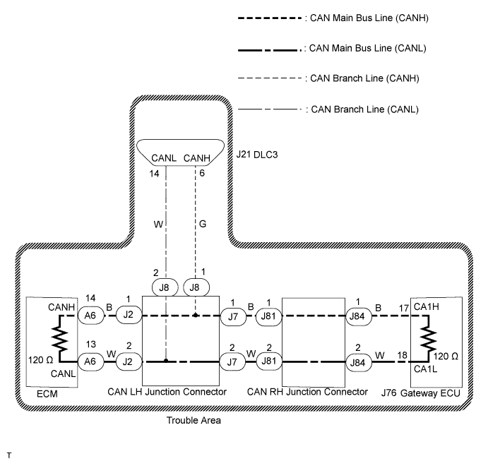
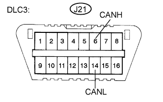
There may be an open circuit in the CAN main bus line and/or the DLC3 branch line when the resistance between terminals 6 (CANH) and 14 (CANL) of the DLC3 is 69 Ω or higher.
| Symptom | Trouble Area |
|---|---|
| Resistance continuity between terminals 6 (CANH) and 14 (CANL) of the DLC3 is 69 Ω or higher. |
|
WIRING DIAGRAM
INSPECTION PROCEDURE
Note
-
Turn the engine switch off before measuring the resistance of CAN bus main wires and CAN bus branch wires.
-
After the engine switch is turned off, check that the key reminder warning system and light reminder warning system are not in operation.
-
Before measuring the resistance, leave the vehicle as is for at least 1 minute and do not operate the engine switch, any other switches, or the doors. If any doors need to be opened in order to check connectors, open the doors and leave them open.
Tech Tips
Operating the engine switch, any switches, or any doors triggers related ECU and sensor communication with the CAN. This communication will cause the resistance value to change.
PROCEDURE
-
CHECK DLC3
-
Turn the engine switch off.
-
Measure the resistance according to the value(s) in the table below.
Standard Resistance Tester Connection Switch Condition Specified Value Result J21-6 (CANH) -J21-14 (CANL) Engine switch off 108 to 132 Ω A J21-6 (CANH) - J21-14 (CANL) Engine switch off 133 Ω or higher B Note
When the measured value is 132 Ω or higher and a CAN communication system diagnostic trouble code is output, there may be a fault besides disconnection of the DLC3 branch line. For that reason, troubleshooting should be performed again from How to Proceed with Troubleshooting Click here after repairing the trouble area.
B 
REPAIR OR REPLACE DLC3 BRANCH LINE OR CONNECTOR (CANH, CANL)
A 
-
-
CHECK FOR OPEN IN CAN BUS MAIN WIRE (CAN BUS CHECK)
-
Perform "CAN Bus Check" using the intelligent tester Click here.
Result Specified Condition Proceed to "Engine" and "ECT" only are not displayed A "Gateway" only is not displayed B Others C
B 
CHECK FOR OPEN IN CAN BUS MAIN WIRE (GATEWAY ECU - CAN LH JUNCTION CONNECTOR) Click here
C
CHECK FOR OPEN IN CAN BUS MAIN WIRE (ECM - CAN LH JUNCTION CONNECTOR) Click here
A
-
-
CHECK FOR OPEN IN CAN BUS MAIN WIRE (ECM - CAN LH JUNCTION CONNECTOR)
-
Turn the engine switch off.
-
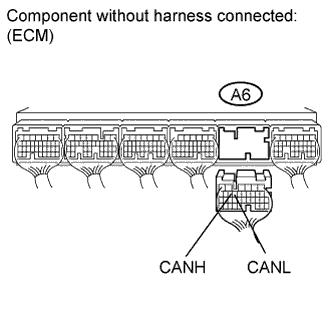
Disconnect the ECM connector (A6).
-
Measure the resistance according to the value(s) in the table below.
Standard Resistance Tester Connection Switch Condition Specified Value A6-14 (CANH) - A6-13 (CANL) Engine switch off 108 to 132 Ω
NG
REPAIR OR REPLACE CAN BUS MAIN WIRE OR CONNECTOR (ECM - CAN LH JUNCTION CONNECTOR)
OK 
REPLACE ECM Click here
-
-
CHECK FOR OPEN IN CAN BUS MAIN WIRE (GATEWAY ECU - CAN LH JUNCTION CONNECTOR)
-
Turn the engine switch off.
-
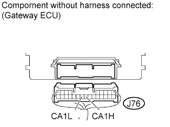
Disconnect the gateway ECU connector (J76).
-
Measure the resistance according to the value(s) in the table below.
Standard Resistance Tester Connection Switch Condition Specified Value J76-17 (CA1H) - J76-18 (CA1L) Engine switch off 108 to 132 Ω
NG
RECONNECT CONNECTOR Click here
OK
REPLACE GATEWAY ECU Click here
-
-
RECONNECT CONNECTOR
-
Reconnect the gateway ECU connector (J76).
NEXT
-
-
CHECK FOR OPEN IN CAN BUS MAIN WIRE (CAN RH JUNCTION CONNECTOR - GATEWAY ECU)
-
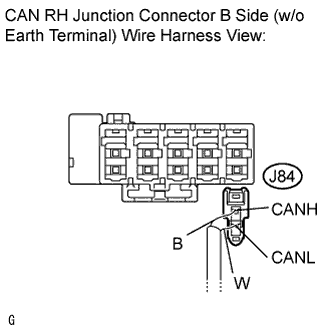
Disconnect the CAN main bus line connector (J84) from the CAN RH junction connector B side (w/o earth terminal).
Note
-
Before disconnecting the connector, make a note of where it is connected.
-
Reconnect the connector to its original position.
-
-
Measure the resistance according to the value(s) in the table below.
Standard Resistance Tester Connection Switch Condition Specified Value J84-1 (CANH) - J84-2 (CANL) Engine switch off 108 to 132 Ω
NG
REPAIR OR REPLACE CAN BUS MAIN WIRE OR CONNECTOR (CAN RH JUNCTION CONNECTOR - GATEWAY ECU)
OK
REPAIR OR REPLACE CAN BUS MAIN WIRE OR CONNECTOR (CAN LH JUNCTION CONNECTOR - CAN RH JUNCTION CONNECTOR)
-
-
CHECK FOR OPEN IN CAN BUS MAIN WIRE (ECM - CAN LH JUNCTION CONNECTOR)
-
Turn the engine switch off.
-
Disconnect the ECM connector (A6).
-
Measure the resistance according to the value(s) in the table below.
Standard Resistance Tester Connection Switch Condition Specified Value A6-14 (CANH) - A6-13 (CANL) Engine switch off 108 to 132 Ω
NG
RECONNECT CONNECTOR Click here
OK
REPLACE ECM Click here
-
-
RECONNECT CONNECTOR
-
Reconnect the ECM connector (A6).
NEXT
-
-
CHECK FOR OPEN IN CAN BUS MAIN WIRE (GATEWAY ECU - CAN LH JUNCTION CONNECTOR)
-
Disconnect the gateway ECU connector (J76).
-
Measure the resistance according to the value(s) in the table below.
Standard Resistance Tester Connection Switch Condition Specified Value J76-17 (CA1H) - J76-18 (CA1L) Engine switch off 108 to 132 Ω
NG
RECONNECT CONNECTOR Click here
OK
REPLACE GATEWAY ECU Click here
-
-
RECONNECT CONNECTOR
-
Reconnect the gateway ECU connector (J76).
NEXT
-
-
CHECK FOR OPEN IN CAN BUS MAIN WIRE (CAN RH JUNCTION CONNECTOR - GATEWAY ECU)
-
Disconnect the CAN main bus line connector (J84) from the CAN RH junction connector B side (w/o earth terminal).
Note
-
Before disconnecting the connector, make a note of where it is connected.
-
Reconnect the connector to its original position.
-
-
Measure the resistance according to the value(s) in the table below.
Standard Resistance Tester Connection Switch Condition Specified Value J84-1 (CANH) - J84-2 (CANL) Engine switch off 108 to 132 Ω
NG
REPAIR OR REPLACE CAN BUS MAIN WIRE OR CONNECTOR (CAN RH JUNCTION CONNECTOR - GATEWAY ECU)
OK
-
-
RECONNECT CONNECTOR
-
Reconnect the CAN main bus line connector (J84) to the CAN RH junction connector B side (w/o earth terminal).
NEXT
-
-
CHECK FOR OPEN IN CAN BUS MAIN WIRE (ECM - CAN LH JUNCTION CONNECTOR)
-
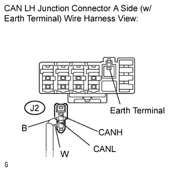
Disconnect the CAN main bus line connector (J2) from the CAN LH junction connector A side (w/ earth terminal).
-
Measure the resistance according to the value(s) in the table below.
Standard Resistance Tester Connection Switch Condition Specified Value J2-1 (CANH) - J2-2 (CANL) Engine switch off 108 to 132 Ω
NG
REPAIR OR REPLACE CAN BUS MAIN WIRE OR CONNECTOR (ECM - CAN LH JUNCTION CONNECTOR)
OK
REPAIR OR REPLACE CAN BUS MAIN WIRE OR CONNECTOR (CAN LH JUNCTION CONNECTOR - CAN RH JUNCTION CONNECTOR)
-