CAN COMMUNICATION SYSTEM ECM Communication Stop Mode
DESCRIPTION
| Detection Item | Symptom | Trouble Area |
|---|---|---|
| ECM Communication Stop Mode |
|
|
Tech Tips
"Engine" and "ECT" refer to the circuit that includes the ECM.
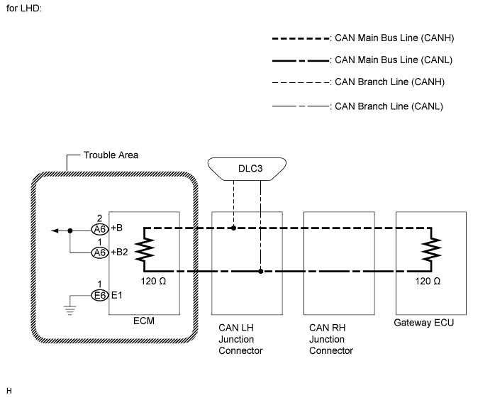
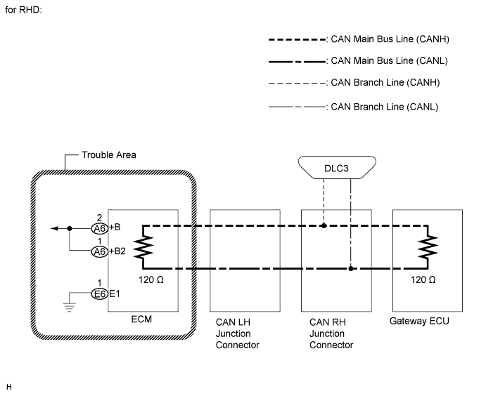
WIRING DIAGRAM
INSPECTION PROCEDURE
Note
-
Turn the engine switch off before measuring the resistance of CAN bus main wires and CAN bus branch wires.
-
After the engine switch is turned off, check that the key reminder warning system and light reminder warning system are not in operation.
-
Before measuring the resistance, leave the vehicle as is for at least 1 minute and do not operate the engine switch, any other switches, or the doors. If any doors need to be opened in order to check connectors, open the doors and leave them open.
Tech Tips
Operating the engine switch, any switches, or any doors triggers related ECU and sensor communication with the CAN. This communication will cause the resistance value to change.
PROCEDURE
-
CHECK ECM POWER SOURCE CIRCUIT
-
Check the ECM power source circuit Click here.
OK The ECM power source circuit is normal. Tech Tips
If there is no abnormality in the ECM power source circuit, replace the ECM.
NG 
REPAIR OR REPLACE ECM POWER SOURCE CIRCUIT
OK 
REPLACE ECM Click here
-