CAN COMMUNICATION SYSTEM TERMINALS OF ECU

Note
-
Turn the engine switch off before measuring the resistance of CAN bus main wires and CAN bus branch wires.
-
After the engine switch is turned off, check that the key reminder warning system and light reminder warning system are not in operating.
-
Before measuring the resistance, leave the vehicle as is for at least 1 minute and do not operate the engine switch, any other switches, or the doors. If any doors need to be opened in order to check connectors, open the doors and leave them open.
Tech Tips
-
Operating the engine switch, any switches, or any doors triggers related ECU and sensor communication with the CAN. This communication will cause the resistance value to change.
-
This section describes the standard CAN values for all CAN related components.
-
CAN junction connector (for LHD)
Tech Tips
-
The connectors connected to the CAN junction connector can be distinguished by the colors of the bus lines and the connecting side of the junction connector.
-
The connectors can be connected to any terminals on the same side.
-
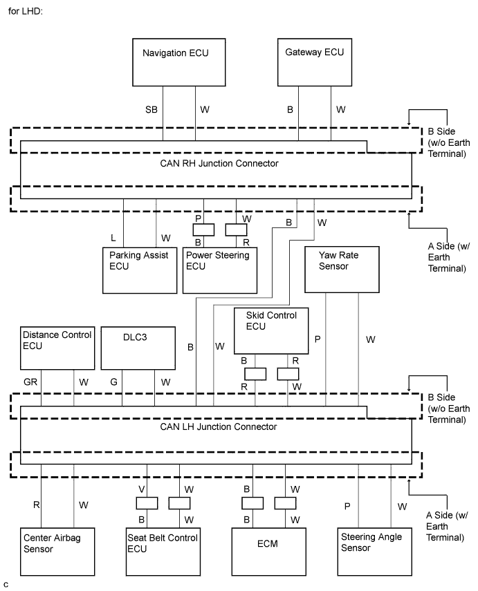
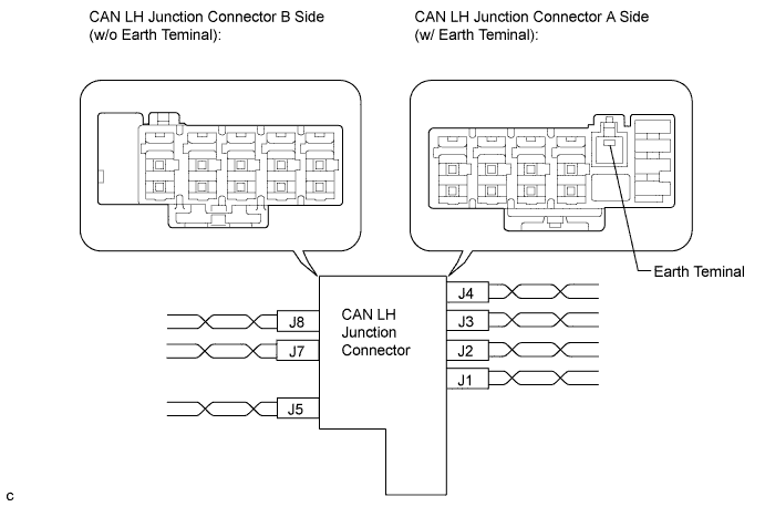
CAN LH junction connector
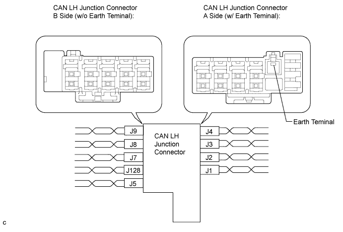
Wiring Color CAN LH Junction Connector A Side (w/ Earth Terminal) Code Color (CANH Side) Color (CANL Side) Steering angle sensor J1 P W ECM J2 B W Seat belt control ECU J3 V W Center airbag sensor J4 R W Wiring Color CAN LH Junction Connector B Side (w/o Earth Terminal) Code Color (CANH Side) Color (CANL Side) Yaw rate sensor J5 P W CAN main bus line (bus line connecting CAN LH junction connector and CAN RH junction connector) J7 B W DLC3 J8 G W Distance control ECU J9 GR W Skid control ECU (Brake actuator assembly) J128 R W -
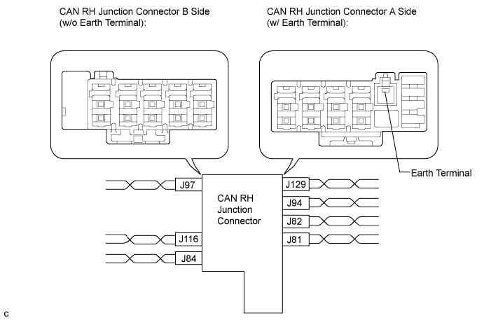
CAN RH junction connector
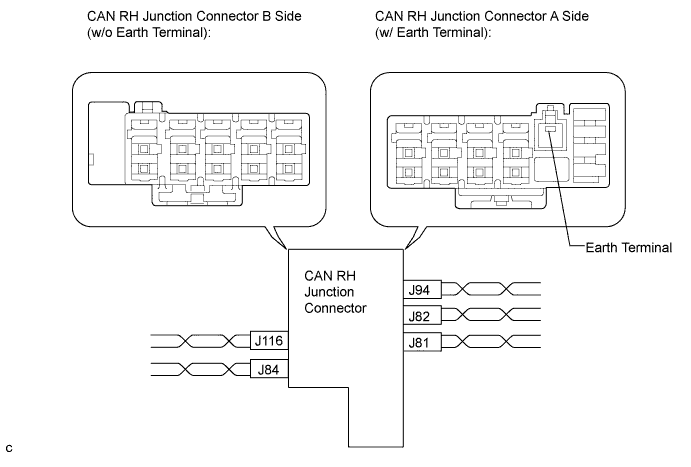
Wiring Color CAN RH Junction Connector A Side (w/ Earth Terminal) Code Color (CANH Side) Color (CANL Side) CAN main bus line (bus line connecting CAN RH junction connector and CAN LH junction connector) J81 B W Power steering ECU J82 P W Parking assist ECU J94 L W Wiring Color CAN RH Junction Connector B Side (w/o Earth Terminal) Code Color (CANH Side) Color (CANL Side) Gateway ECU J84 B W Navigation ECU (Display and navigation module display) J116 SB W -
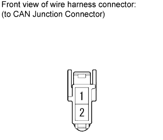
CAN junction connector terminals
Terminal Terminal symbol 1 CANH 2 CANL -
Wiring diagram for identifying CAN junction connector connectors
-
-
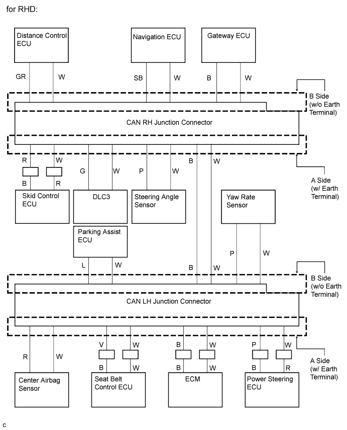
CAN junction connector (for RHD)
Tech Tips
-
The connectors connected to the CAN junction connector can be distinguished by the colors of the bus lines and the connecting side of the junction connector.
-
The connectors can be connected to any terminals on the same side.
-
CAN LH junction connector
Wiring Color CAN LH Junction Connector A Side (w/ Earth Terminal) Code Color (CANH Side) Color (CANL Side) Power steering ECU J1 P W ECM J2 B W Seat belt control ECU J3 V W Center airbag sensor J4 R W Wiring Color CAN LH Junction Connector B Side (w/o Earth Terminal) Code Color (CANH Side) Color (CANL Side) Yaw rate sensor J5 P W CAN main bus line (bus line connecting CAN LH junction connector and CAN RH junction connector) J7 B W Parking assist ECU J8 L W -
CAN RH junction connector
Wiring Color CAN RH Junction Connector A Side (w/ Earth Terminal) Code Color (CANH Side) Color (CANL Side) CAN main bus line (bus line connecting CAN RH junction connector and CAN LH junction connector) J81 B W Steering angle sensor J82 P W DLC3 J94 G W Skid control ECU (Brake actuator assembly) J129 R W Wiring Color CAN RH Junction Connector B Side (w/o Earth Terminal) Code Color (CANH Side) Color (CANL Side) Gateway ECU J84 B W Navigation ECU (Display and navigation module display) J116 SB W Distance control ECU J97 GR W -
CAN junction connector terminals
Terminal Terminal symbol 1 CANH 2 CANL -
Wiring diagram for identifying CAN junction connector connectors
-
-
DLC3
-
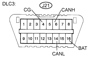
Measure the resistance according to the value(s) in the table below.
-
-
SKID CONTROL ECU (BRAKE ACTUATOR ASSEMBLY)
-
Disconnect the connector from the skid control ECU.
-
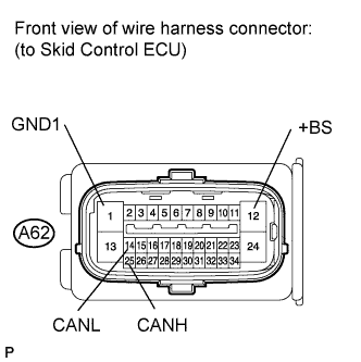
Measure the resistance according to the value(s) in the table below.
-
-
STEERING ANGLE SENSOR
-
Disconnect the connector from the steering angle sensor.
-
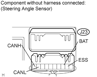
Measure the resistance according to the value(s) in the table below.
-
-
YAW RATE SENSOR
-
Disconnect the connector from the yaw rate sensor.
-
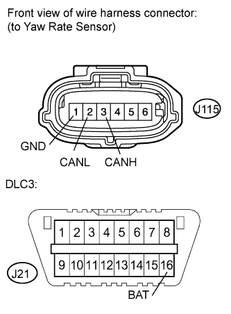
Measure the resistance according to the value(s) in the table below.
-
-
DISTANCE CONTROL ECU
-
Disconnect the connector from the distance control ECU.
-
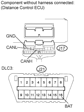
Measure the resistance according to the value(s) in the table below.
-
-
SEAT BELT CONTROL ECU
-
Disconnect the connector from the seat belt control ECU.
-
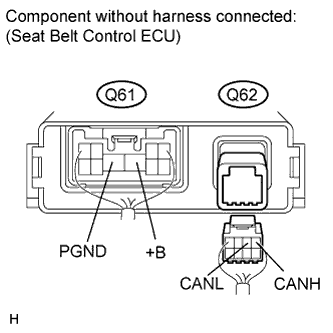
Measure the resistance according to the value(s) in the table below.
-
-
PARKING ASSIST ECU
-
Disconnect the connector from the parking assist ECU.
-
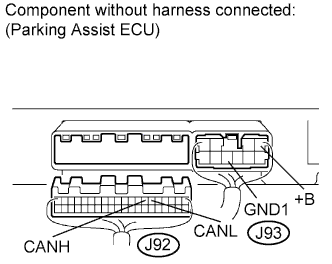
Measure the resistance according to the value(s) in the table below.
-
-
POWER STEERING ECU
-
Disconnect the connector from the power steering ECU.
-
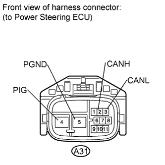
Measure the resistance according to the value(s) in the table below.
-
-
CENTER AIRBAG SENSOR
-
Disconnect the connector from the center airbag sensor.
-
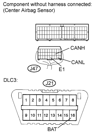
Measure the resistance according to the value(s) in the table below.
-
-
ECM
-
Disconnect the connector from the ECM.
-
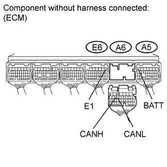
Measure the resistance according to the value(s) in the table below.
-
-
GATEWAY ECU
-
Disconnect the connector from the gateway ECU.
-
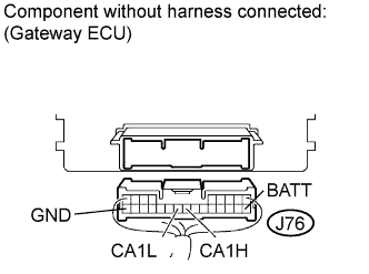
Measure the resistance according to the value(s) in the table below.
-
-
NAVIGATION ECU (DISPLAY AND NAVIGATION MODULE DISPLAY)
-
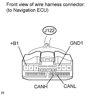
Disconnect the display and navigation module display (Navigation ECU) connector.
-
Measure the resistance according to the value(s) in the table below.
-