MULTIPLEX COMMUNICATION SYSTEM, Diagnostic DTC:B1266, B1267

| DTC Code | DTC Name |
|---|---|
| B1266 | Short to B+ in Instrument Panel System Communication Bus Malfunction |
| B1267 | Short to GND in Instrument Panel System Communication Bus Malfunction |
DESCRIPTION
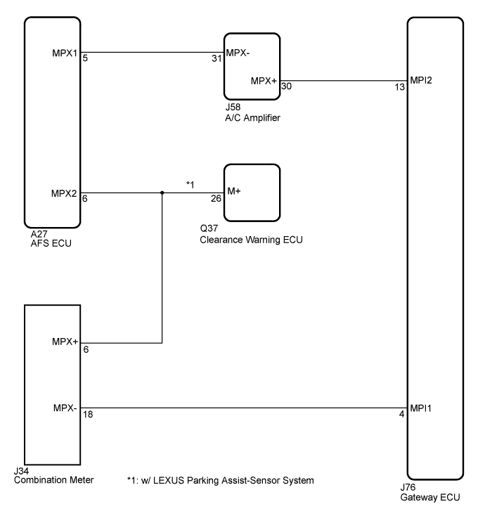
If a +B short circuit or body ground short circuit is detected on the instrument panel system communication bus (BEAN), the instrument panel system communication bus (BEAN) is disabled and a DTC code is output.
| DTC No. | DTC Detection Condition | Trouble Area |
|---|---|---|
| B1266 | Instrument panel system communication circuit and +B battery system short |
|
| B1267 | Instrument panel system communication circuit and body ground short |
|
WIRING DIAGRAM
INSPECTION PROCEDURE
PROCEDURE
-
CHECK FOR DTC (COMBINATION METER)
-
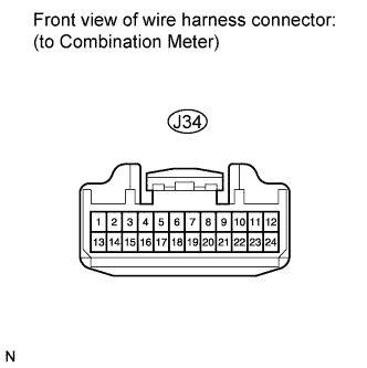
Disconnect the J34 connector.
-
Turn the engine switch on (IG).
-
Clear the DTC Click here.
-
Check for DTCs Click here.
OK DTCs B1266 and B1267 are not output.
NG 
CHECK FOR DTC (A/C AMPLIFIER) Click here
OK 
REPLACE COMBINATION METER Click here
-
-
CHECK FOR DTC (A/C AMPLIFIER)
-
Reconnect the J34 connector.
-
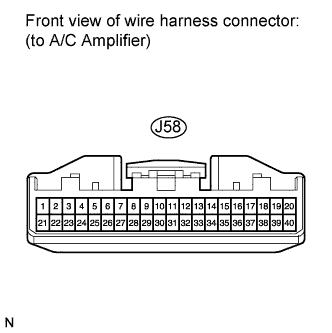
Disconnect the J58 connector.
-
Turn the engine switch on (IG).
-
Clear the DTC Click here.
-
Check for DTCs Click here.
OK DTCs B1266 and B1267 are not output.
NG
CHECK HARNESS, CONNECTOR AND EACH ECU Click here
OK
REPLACE A/C AMPLIFIER Click here
-
-
CHECK HARNESS, CONNECTOR AND EACH ECU
-
Disconnect the J34 connector.
-
Turn the engine switch on (IG).
-
Clear the DTC Click here.
-
Check for DTCs Click here.
OK DTCs B1266 and B1267 are not output.
NG
CHECK HARNESS AND CONNECTOR (COMBINATION METER - GATEWAY ECU) Click here
OK 
-
-
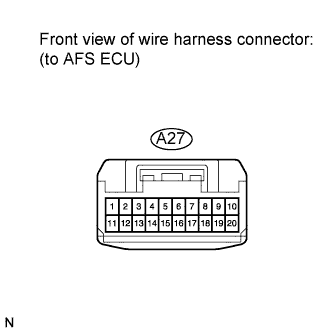
CHECK FOR DTC (AFS ECU)
-
Reconnect the J34 and J58 connectors.
-
Disconnect the A27 connector.
-
Turn the engine switch on (IG).
-
Clear the DTC Click here.
-
Check for DTCs Click here.
OK DTCs B1266 and B1267 are not output.
NG
CHECK HARNESS AND CONNECTOR (AFS ECU - A/C AMPLIFIER) Click here
OK
REPLACE AFS ECU Click here
-
-
CHECK HARNESS AND CONNECTOR (AFS ECU - A/C AMPLIFIER)
-
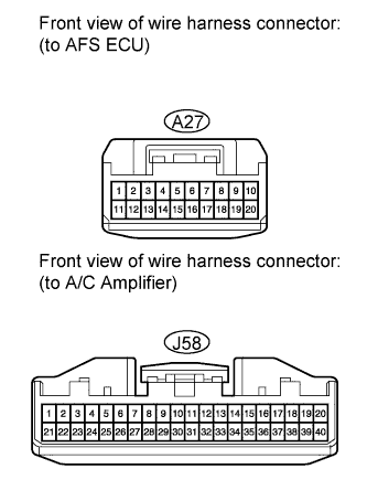
Disconnect the J58 connector.
-
Turn the engine switch on (IG).
-
Clear the DTC Click here.
-
Check for DTCs Click here.
OK DTCs B1266 and B1267 are not output. -
Proceed to next step based on the inspection result.
Result Result Proceed to OK A NG (w/ Intuitive Parking Assist System) B NG (w/o Intuitive Parking Assist System) C
B
CHECK FOR DTC (CLEARANCE WARNING ECU) Click here
C 
REPAIR OR REPLACE HARNESS OR CONNECTOR (AFS ECU - COMBINATION METER)
A
REPAIR OR REPLACE HARNESS OR CONNECTOR (AFS ECU - AIR CONDITIONING AMPLIFIER)
-
-
CHECK FOR DTC (CLEARANCE WARNING ECU)
-
Reconnect the A27 and J58 connectors.
-
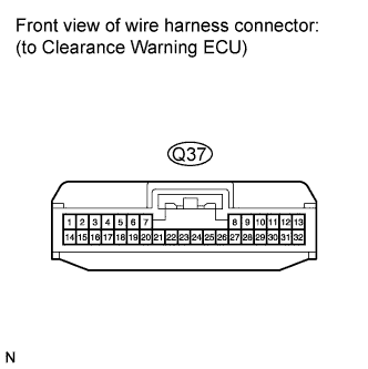
Disconnect the Q37 connector.
-
Turn the engine switch on (IG).
-
Clear the DTC Click here.
-
Check for DTCs Click here.
OK DTCs B1266 and B1267 are not output.
NG
REPAIR OR REPLACE HARNESS OR CONNECTOR
OK
REPLACE CLEARANCE WARNING ECU Click here
-
-
CHECK HARNESS AND CONNECTOR (COMBINATION METER - GATEWAY ECU)
-
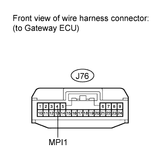
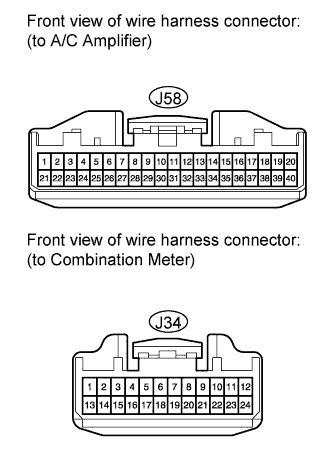
Disconnect the J76 and J58 connector.
-
Measure the voltage and resistance according to the value(s) in the table below.
Standard Voltage Tester Connection Condition Specified Condition J76-4 (MPI1) - Body ground Always Below 1 V Standard Resistance Tester Connection Condition Specified Condition J76-4 (MPI1) - Body ground Always 10 kΩ or higher
NG
REPAIR OR REPLACE HARNESS AND CONNECTOR (TIRE PRESSURE WARNING ECU - GATEWAY ECU)
OK
-
-
CHECK HARNESS AND CONNECTOR (A/C AMPLIFIER - GATEWAY ECU)
-

Disconnect the J58 connector.
-
Measure the voltage and resistance according to the value(s) in the table below.
Standard Voltage Tester Connection0 Condition Specified Condition J76-13 (MPI2) - Body ground Always Below 11 V Standard Resistance Tester Connection Condition Specified Condition J76-13 (MPI2) - Body ground Always 10 kΩ or higher
NG
REPAIR OR REPLACE HARNESS OR CONNECTOR (A/C AMPLIFIER - GATEWAY ECU)
OK
REPLACE GATEWAY ECU
-