MULTIPLEX COMMUNICATION SYSTEM, Diagnostic DTC:B1262

| DTC Code | DTC Name |
|---|---|
| B1262 | A/C ECU Communication Stop |
DESCRIPTION
-
This DTC is detected if communication between the A/C amplifier (A/C ECU) and gateway ECU stops for more than 10 seconds.
| DTC No. | DTC Detection Condition | Trouble Area |
|---|---|---|
| B1262 | A/C amplifier (A/C ECU) communication stops |
|
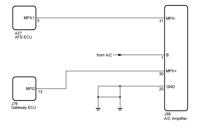
WIRING DIAGRAM
INSPECTION PROCEDURE
Tech Tips
If "+B of GND short malfunction of communication bus" DTCs (B1266 and B1267) are detected at the same time as "communication stop" DTC B1262, repair the "+B or GND short malfunction of communication bus" DTCs first Click here.
PROCEDURE
-
CHECK FUSE (A/C)
-
Remove the A/C fuse from the main body ECU LH (cowl side junction block LH).
-
Measure the resistance according to the value(s) in the table below.
Standard Resistance Tester Connection Condition Specified Condition A/C fuse Always Below 1 Ω
NG 
REPLACE FUSE
OK 
-
-
CHECK HARNESS AND CONNECTOR (A/C AMPLIFIER - BATTERY AND BODY GROUND)
-
Disconnect the J58 ECU connector.
-
Measure the voltage and resistance according to the value(s) in the table below.
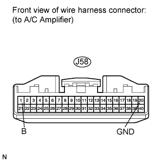
Standard Voltage Tester Connection Condition Specified Condition J58-1 (B) - Body ground Always 11 to 14 V Standard Resistance Tester Connection Condition Specified Condition J58-20 (GND) - Body ground Always Below 1 Ω
NG
REPAIR OR REPLACE HARNESS OR CONNECTOR (A/C AMPLIFIER - BATTERY AND BODY GROUND)
OK
-
-
CHECK HARNESS AND CONNECTOR (COMMUNICATION LINE)
-
Disconnect the J58, A27 and J76 connectors.
-
Measure the resistance according to the value(s) in the table below.
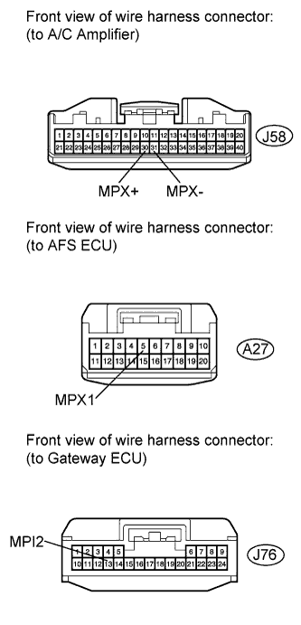
Standard Resistance Tester Connection Condition Specified Condition J58-31 (MPX-) - A27-5 (MPX1) Always Below 1 Ω J58-30 (MPX+) - J76-13 (MPI2) Always Below 1 Ω
NG
REPAIR OR REPLACE HARNESS OR CONNECTOR (COMMUNICATION LINE)
OK 
REPLACE A/C AMPLIFIER Click here
-