MULTIPLEX COMMUNICATION SYSTEM, Diagnostic DTC:B1214, B1215

| DTC Code | DTC Name |
|---|---|
| B1214 | Short to B+ in Door System Communication Bus Malfunction |
| B1215 | Short to GND in Door System Communication Bus Malfunction |
DESCRIPTION
-
If a +B short circuit or body ground short circuit is detected on the door system communication bus (BEAN), BEAN is disabled and a DTC is stored.
| DTC No. | DTC Detection Condition | Trouble Area |
|---|---|---|
| B1214 | Door system communication circuit and +B battery system short |
|
| B1215 | Door system communication circuit and body ground short |
|
Tech Tips
*1: w/ Sliding Roof System
*2: w/ Double Locking System
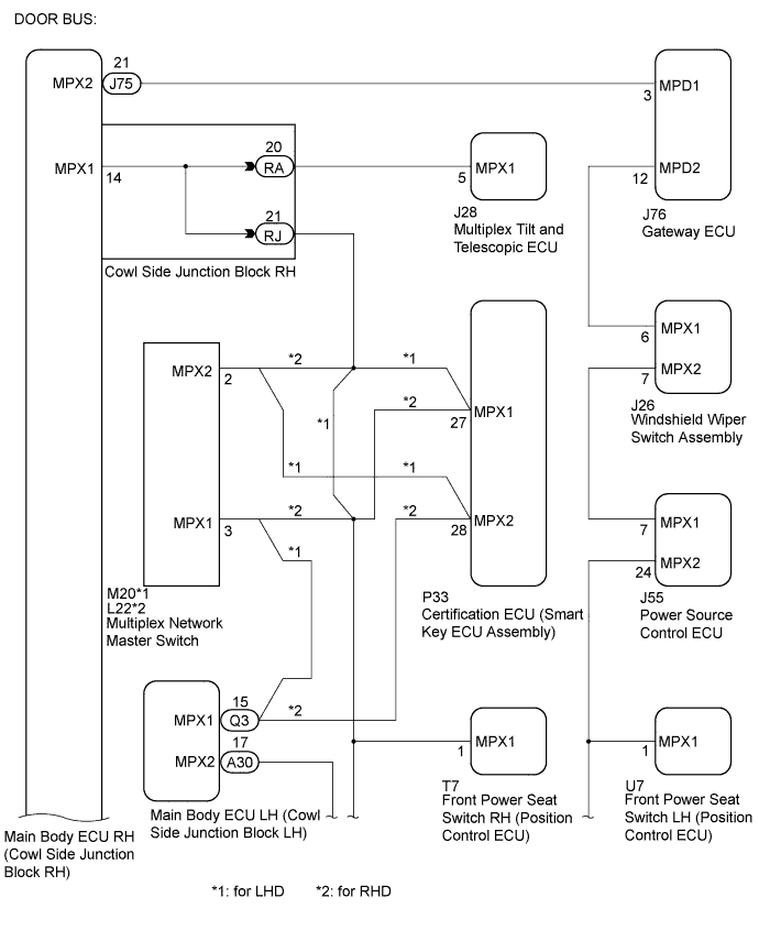
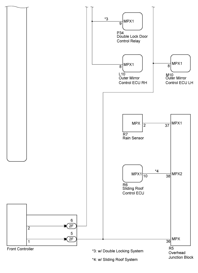
WIRING DIAGRAM
INSPECTION PROCEDURE
PROCEDURE
-
CHECK FOR DTC (MAIN BODY ECU RH)
-
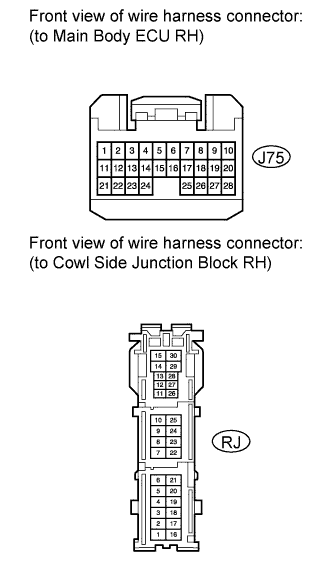
Disconnect the J75 and RJ connector.
-
Connect the intelligent tester to the DLC3.
-
Turn the engine switch on (IG).
-
Clear the DTC Click here.
-
Check for DTCs Click here.
OK DTCs B1214 and B1215 are not output.
NG 
CHECK FOR DTC (FRONT CONTROLLER) Click here
OK 
-
-
CHECK FOR DTC (MULTIPLEX TILT AND TELESCOPIC ECU)
-
Reconnect the J75 and RJ connectors.
-
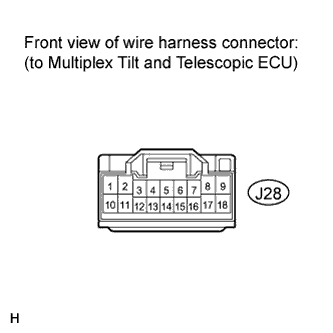
Disconnect the J28 connector.
-
Turn the engine switch on (IG).
-
Clear the DTC Click here.
-
Check for DTCs Click here.
OK DTCs B1214 and B1215 are not output.
NG
CHECK HARNESS AND CONNECTOR (MULTIPLEX TILT AND TELESCOPIC ECU - MAIN BODY ECU RH) Click here
OK 
REPLACE MULTIPLEX TILT AND TELESCOPIC ECU Click here
-
-
CHECK HARNESS AND CONNECTOR (MULTIPLEX TILT AND TELESCOPIC ECU - MAIN BODY ECU RH)
-
Reconnect the J28 connector.
-
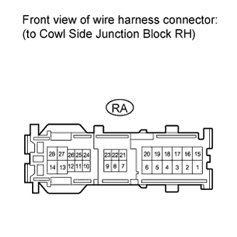
Disconnect the RA connector.
-
Turn the engine switch on (IG).
-
Clear the DTC Click here.
-
Check for DTCs Click here.
OK DTCs B1214 and B1215 are not output.
NG 
REPLACE MAIN BODY ECU RH (COWL SIDE JUNCTION BLOCK RH)
OK
REPAIR OR REPLACE HARNESS OR CONNECTOR (MULTIPLEX TILT AND TELESCOPIC ECU - MAIN BODY ECU RH)
-
-
CHECK FOR DTC (FRONT CONTROLLER)
-
Reconnect the J75 and RJ connectors.
-
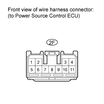
Disconnect the 2F connector.
-
Turn the engine switch on (IG).
-
Clear the DTC Click here.
-
Check for DTCs Click here.
OK DTCs B1214 and B1215 are not output.
NG
CHECK HARNESS, CONNECTOR AND EACH ECU Click here
OK
REPLACE FRONT CONTROLLER
-
-
CHECK HARNESS, CONNECTOR AND EACH ECU
-
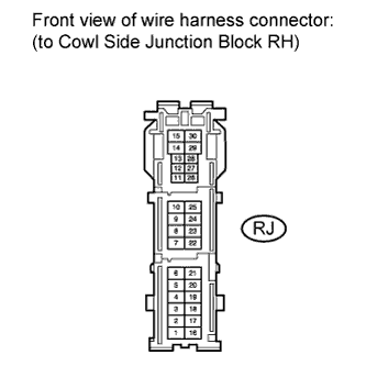
Disconnect the RJ connector.
-
Turn the engine switch on (IG).
-
Clear the DTC Click here.
-
Check for DTCs Click here.
Result Result Proceed to DTCs B1214 and B1215 are not output (for LHD) A DTCs B1214 and B1215 are not output (for RHD) B DTCs B1214 or B1215 is output C OK DTCs B1214 and B1215 are not output.
B
CHECK FOR DTC (OUTER MIRROR CONTROL ECU RH) Click here
C
CHECK HARNESS, CONNECTOR AND EACH ECU Click here
A
-
-
CHECK FOR DTC (MULTIPLEX NETWORK MASTER SWITCH)
-
Reconnect the RJ and 2F connectors.
-
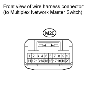
Disconnect the M20 connector.
-
Turn the engine switch on (IG).
-
Clear the DTC Click here.
-
Check for DTCs Click here.
OK DTCs B1214 and B1215 are not output.
NG
CHECK HARNESS, CONNECTOR AND EACH ECU Click here
OK
REPLACE MULTIPLEX NETWORK MASTER SWITCH Click here
-
-
CHECK HARNESS, CONNECTOR AND EACH ECU
-
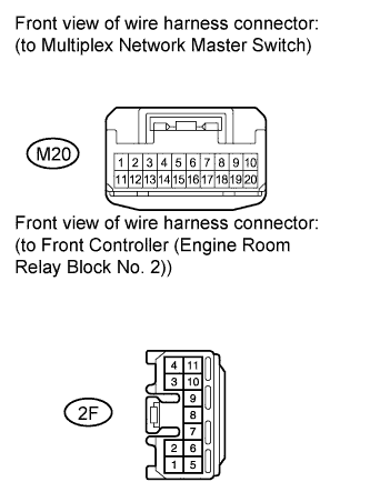
Disconnect the 2F connector.
-
Turn the engine switch on (IG).
-
Clear the DTC Click here.
-
Check for DTCs Click here.
OK DTCs B1214 and B1215 are not output.
NG
CHECK FOR DTC (FRONT POWER SEAT SWITCH RH (POSITION CONTROL ECU)) Click here
OK
-
-
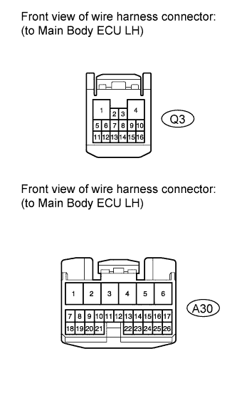
CHECK FOR DTC (MAIN BODY ECU LH (COWL SIDE JUNCTION BLOCK LH))
-
Reconnect the M20 and 2F connectors.
-
Disconnect the A30 and Q3 connectors.
-
Turn the engine switch on (IG).
-
Clear the DTC Click here.
-
Check for DTCs Click here.
OK DTCs B1214 and B1215 are not output.
NG
CHECK HARNESS AND CONNECTOR (MULTIPLEX NETWORK MASTER SWITCH - MAIN BODY ECU LH) Click here
OK
REPLACE MAIN BODY ECU LH (COWL SIDE JUNCTION BLOCK LH)
-
-
CHECK HARNESS AND CONNECTOR (MULTIPLEX NETWORK MASTER SWITCH - MAIN BODY ECU LH)
-
Disconnect the M20 connector.
-
Turn the engine switch on (IG).
-
Clear the DTC Click here.
-
Check for DTCs Click here.
OK DTCs B1214 and B1215 are not output.
NG
REPAIR OR REPLACE HARNESS OR CONNECTOR (MAIN BODY ECU LH - FRONT CONTROLLER)
OK
REPAIR OR REPLACE HARNESS OR CONNECTOR (MULTIPLEX NETWORK MASTER SWITCH - MAIN BODY ECU LH)
-
-
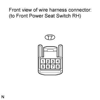
CHECK FOR DTC (FRONT POWER SEAT SWITCH RH (POSITION CONTROL ECU))
-
Reconnect the M20 and 2F connectors.
-
Disconnect the T7 connector.
-
Turn the engine switch on (IG).
-
Clear the DTC Click here.
-
Check for DTCs Click here.
OK DTCs B1214 and B1215 are not output.
NG
CHECK FOR DTC (DOUBLE LOCK DOOR CONTROL RELAY) Click here
OK
REPLACE FRONT POWER SEAT SWITCH RH (POSITION CONTROL ECU RH) Click here
-
-
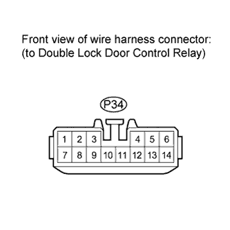
CHECK FOR DTC (DOUBLE LOCK DOOR CONTROL RELAY)
-
Reconnect the T7 connector.
-
Disconnect the P34 connector.
-
Turn the engine switch on (IG).
-
Clear the DTC Click here.
-
Check for DTCs Click here.
OK DTCs B1214 and B1215 are not output.
NG
CHECK FOR DTC (OUTER MIRROR CONTROL ECU RH) Click here
OK
REPLACE DOUBLE LOCK DOOR CONTROL RELAY
-
-
CHECK FOR DTC (OUTER MIRROR CONTROL ECU RH)
-
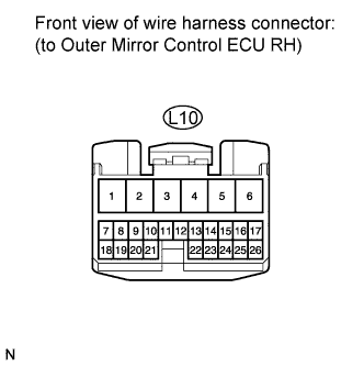
Disconnect the L10 connector.
-
Turn the engine switch on (IG).
-
Clear the DTC Click here.
-
Check for DTCs Click here.
OK DTCs B1214 and B1215 are not output.
NG
CHECK HARNESS AND CONNECTOR (MULTIPLEX NETWORK MASTER SWITCH - CERTIFICATION ECU) Click here
OK
REPLACE OUTER MIRROR CONTROL ECU RH Click here
-
-
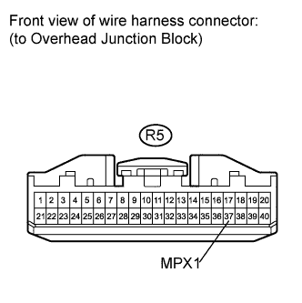
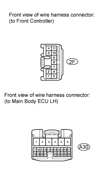
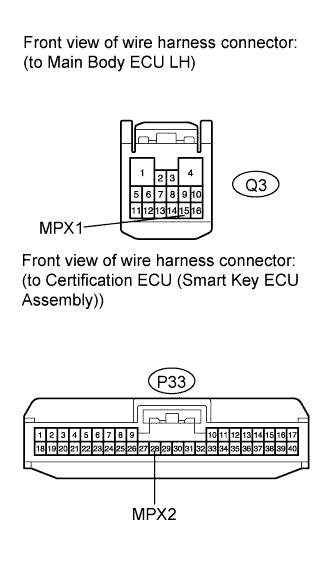
CHECK HARNESS AND CONNECTOR (MULTIPLEX NETWORK MASTER SWITCH - CERTIFICATION ECU)
-
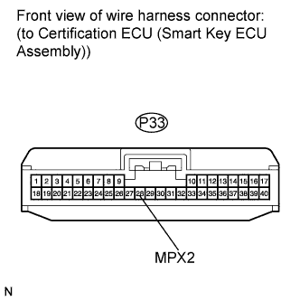
Disconnect the M20 and P33 connectors.
-
Measure the voltage and resistance according to the value(s) in the table below.
Standard Voltage Tester Connection Condition Specified Condition P33-28 (MPX2) - Body ground Always Below 1 V Standard Resistance Tester Connection Condition Specified Condition P33-28 (MPX2) - Body ground Always 10 kΩ or higher
NG
REPAIR OR REPLACE HARNESS OR CONNECTOR (MULTIPLEX NETWORK MASTER SWITCH - CERTIFICATION ECU)
OK
-
-
CHECK HARNESS AND CONNECTOR
-
Reconnect the M20 connector.
-
Disconnect the RJ connector.
-
Measure the voltage and resistance according to the value(s) in the table below.
Standard Voltage Tester Connection Condition Specified Condition RJ-21 - Body ground Always Below 1 V Standard Resistance Tester Connection Condition Specified Condition RJ-21 - Body ground Always 10 kΩ or higher
NG
REPAIR OR REPLACE HARNESS OR CONNECTOR
OK
REPLACE CERTIFICATION ECU (SMART KEY ECU ASSEMBLY)
-
-
CHECK HARNESS, CONNECTOR AND EACH ECU
-
Reconnect the RJ and 2F connectors.
-
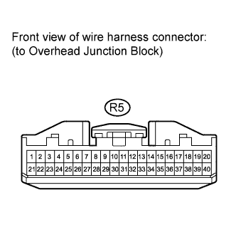
Disconnect the R5 connector.
-
Turn the engine switch on (IG).
-
Clear the DTC Click here.
-
Check for DTCs Click here.
OK DTCs B1214 and B1215 are not output. -
Proceed to next step based on the inspection result.
Result Result Proceed to OK (w/ Sliding roof system) A OK (w/o Sliding roof system) B NG C
B
CHECK FOR DTC (RAIN SENSOR) Click here
C
CHECK FOR DTC (FRONT POWER SEAT SWITCH LH (POSITION CONTROL ECU)) Click here
A
-
-
CHECK FOR DTC (SLIDING ROOF CONTROL ECU)
-
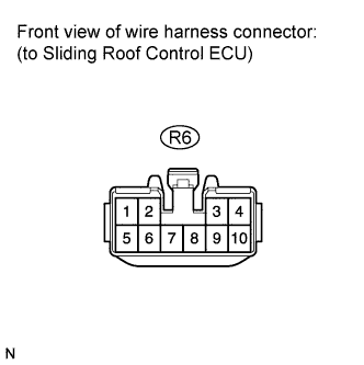
Reconnect the R5 connector.
-
Disconnect the R6 connector.
-
Turn the engine switch on (IG).
-
Clear the DTC Click here.
-
Check for DTCs Click here.
OK DTCs B1214 and B1215 are not output.
NG
CHECK HARNESS AND CONNECTOR (SLIDING ROOF ECU - OVERHEAD JUNCTION BLOCK) Click here
OK
REPLACE SLIDING ROOF CONTROL ECU Click here
-
-
CHECK HARNESS AND CONNECTOR (SLIDING ROOF ECU - OVERHEAD JUNCTION BLOCK)
-
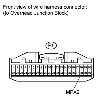
Disconnect the R5 connector.
-
Measure the voltage and resistance according to the value(s) in the table below.
Standard Voltage Tester Connection Condition Specified Condition R5-38 (MPX2) - Body ground Always Below 1 V Standard Resistance Tester Connection Condition Specified Condition R5-38 (MPX2) - Body ground Always 10 kΩ or higher
NG
REPAIR OR REPLACE HARNESS OR CONNECTOR (SLIDING ROOF ECU - OVER HEAD JUNCTION BLOCK)
OK
-
-
CHECK FOR DTC (RAIN SENSOR)
-
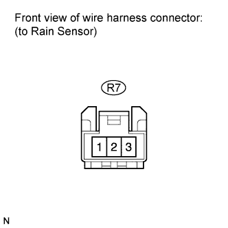
Reconnect the R5 and R6* connectors.
-
Disconnect the R7 connector.
-
Turn the engine switch on (IG).
-
Clear the DTC Click here.
-
Check for DTCs Click here.
Tech Tips
*: w/ Sliding Roof System
OK DTCs B1214 and B1215 are not output.
NG
CHECK HARNESS AND CONNECTOR (RAIN SENSOR - OVERHEAD JUNCTION BLOCK) Click here
OK
REPLACE RAIN SENSOR Click here
-
-
CHECK HARNESS AND CONNECTOR (RAIN SENSOR - OVERHEAD JUNCTION BLOCK)
-
Disconnect the R5 connector.
-
Measure the voltage and resistance according to the value(s) in the table below.
Standard Voltage Tester Connection Condition Specified Condition R5-37 (MPX1) - Body ground Always Below 1 V Standard Resistance Tester Connection Condition Specified Condition R5-37 (MPX1) - Body ground Always 10 kΩ or higher
NG
REPAIR OR REPLACE HARNESS OR CONNECTOR (RAIN SENSOR - OVERHEAD JUNCTION BLOCK)
OK
REPLACE OVERHEAD JUNCTION BLOCK
-
-
CHECK FOR DTC (FRONT POWER SEAT SWITCH LH (POSITION CONTROL ECU))
-
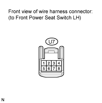
Reconnect the R5 connector.
-
Disconnect the U7 connector.
-
Turn the engine switch on (IG).
-
Clear the DTC Click here.
-
Check for DTCs Click here.
OK DTCs B1214 and B1215 are not output.
NG
CHECK FOR DTC (OUTER MIRROR CONTROL ECU LH) Click here
OK
REPLACE FRONT POWER SEAT SWITCH LH (POSITION CONTROL ECU) Click here
-
-
CHECK FOR DTC (OUTER MIRROR CONTROL ECU LH)
-
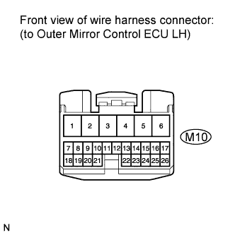
Reconnect the U7 connector.
-
Disconnect the M10 connector.
-
Turn the engine switch on (IG).
-
Clear the DTC Click here.
-
Check for DTCs Click here.
OK DTCs B1214 and B1215 are not output.
NG
CHECK FOR DTC (WINDSHIELD WIPER SWITCH ASSEMBLY) Click here
OK
REPLACE OUTER MIRROR CONTROL ECU LH Click here
-
-
CHECK FOR DTC (WINDSHIELD WIPER SWITCH ASSEMBLY)
-
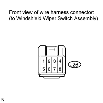
Reconnect the M10 connector.
-
Disconnect the J26 connector.
-
Turn the engine switch on (IG).
-
Clear the DTC Click here.
-
Check for DTCs Click here.
OK DTCs B1214 and B1215 are not output.
NG
CHECK HARNESS AND CONNECTOR (POWER SOURCE CONTROL ECU - FRONT CONTROLLER) Click here
OK
REPLACE WINDSHIELD WIPER SWITCH ASSEMBLY Click here
-
-
CHECK HARNESS AND CONNECTOR (POWER SOURCE CONTROL ECU - FRONT CONTROLLER)
-
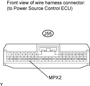
Reconnect the J26 connector.
-
Disconnect the J55 and 2F connectors.
-
Measure the voltage and resistance according to the value(s) in the table below.
Standard Voltage Tester Connection Condition Specified Condition J55-24 (MPX2) - Body ground Always Below 1 V Standard Resistance Tester Connection Condition Specified Condition J55-24 (MPX2) - Body ground Always 10 kΩ or higher
NG
REPAIR OR REPLACE HARNESS OR CONNECTOR (POWER SOURCE CONTROL ECU - FRONT CONTROLLER)
OK
-
-
CHECK HARNESS AND CONNECTOR (WINDSHIELD WIPER SWITCH - POWER SOURCE CONTROL ECU)
-
Reconnect the 2F connector.
-
Disconnect the J26 connector.
-
Measure the voltage and resistance according to the value(s) in the table below.
Standard Voltage Tester Connection Condition Specified Condition J26-7 (MPX2) - Body ground Always Below 1 V Standard Resistance Tester Connection Condition Specified Condition J26-7 (MPX2) - Body ground Always 10 kΩ or higher
NG
REPAIR OR REPLACE HARNESS OR CONNECTOR (WINDSHIELD WIPER SWITCH - POWER SOURCE CONTROL ECU)
OK
-
-
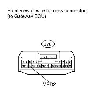
CHECK HARNESS AND CONNECTOR (WINDSHIELD WIPER SWITCH - GATEWAY ECU)
-
Reconnect the J55 connector
-
Disconnect the J76 connector.
-
Measure the voltage and resistance according to the value(s) in the table below.
Standard Voltage Tester Connection Condition Specified Condition J76-12 (MPD2) - Body ground Always Below 1 V Standard Resistance Tester Connection Condition Specified Condition J76-12 (MPD2) - Body ground Always 10 kΩ or higher
NG
REPAIR OR REPLACE HARNESS OR CONNECTOR (WINDSHIELD WIPER SWITCH - GATEWAY ECU)
OK
-
-
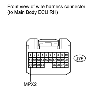
CHECK HARNESS AND CONNECTOR (GATEWAY ECU - MAIN BODY ECU RH (COWL SIDE JUNCTION BLOCK RH))
-
Reconnect the J26 connector.
-
Disconnect the J75 connector.
-
Measure the voltage and resistance according to the value(s) in the table below.
Standard Voltage Tester Connection Condition Specified Condition J75-21 (MPX2) - Body ground Always Below 1 V Standard Resistance Tester Connection Condition Specified Condition J75-21 (MPX2) - Body ground Always 10 kΩ or higher
NG
REPAIR OR REPLACE HARNESS OR CONNECTOR (GATEWAY ECU - MAIN BODY ECU RH (COWL SIDE JUNCTION BLOCK RH))
OK
-
-
REPLACE GATEWAY ECU
-
Reconnect the J75 connector.
-
Replace the Gateway ECU with a normally functioning ECU.
-
Clear the DTC Click here.
-
Check for DTCs Click here.
OK DTCs B1214 and B1215 are not output.
NG
REPLACE POWER SOURCE CONTROL ECU
OK
END (GATEWAY ECU WAS DEFECTIVE)
-
-
CHECK FOR DTC (OUTER MIRROR CONTROL ECU RH)
-
Reconnect the RJ and 2F connectors.
-
Disconnect the L10 connector.
-
Turn the engine switch on (IG).
-
Clear the DTC Click here.
-
Check for DTCs Click here.
OK DTCs B1214 and B1215 are not output. -
Proceed to next step based on the inspection result.
Result Result Proceed to OK A NG (w/ Double locking system) B NG (w/o Double locking system) C
B
CHECK FOR DTC (DOUBLE LOCK DOOR CONTROL RELAY) Click here
C
CHECK FOR DTC (FRONT POWER SEAT SWITCH RH (POSITION CONTROL ECU)) Click here
A
REPLACE OUTER MIRROR CONTROL ECU Click here
-
-
CHECK FOR DTC (DOUBLE LOCK DOOR CONTROL RELAY)
-
Reconnect the L10 connector.
-
Disconnect the P34 connector.
-
Turn the engine switch on (IG).
-
Clear the DTC Click here.
-
Check for DTCs Click here.
OK DTCs B1214 and B1215 are not output.
NG
CHECK FOR DTC (FRONT POWER SEAT SWITCH RH (POSITION CONTROL ECU)) Click here
OK
REPLACE DOUBLE LOCK DOOR CONTROL RELAY
-
-
CHECK FOR DTC (FRONT POWER SEAT SWITCH RH (POSITION CONTROL ECU))
-
Reconnect the P34 connector.
-
Disconnect the T7 connector.
-
Clear the DTC Click here.
-
Check for DTCs Click here.
OK DTCs B1214 and B1215 are not output.
NG
CHECK FOR DTC (MULTIPLEX NETWORK MASTER SWITCH) Click here
OK
REPLACE FRONT POWER SEAT SWITCH RH Click here
-
-
CHECK FOR DTC (MULTIPLEX NETWORK MASTER SWITCH)
-
Reconnect the T7 connector.
-
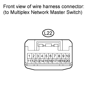
Disconnect the L22 connector.
-
Clear the DTC Click here.
-
Check for DTCs Click here.
OK DTCs B1214 and B1215 are not output.
NG
CHECK HARNESS AND CONNECTOR (MAIN BODY ECU RH - POWER WINDOW MASTER SWITCH) Click here
OK
REPLACE MULTIPLEX NETWORK MASTER SWITCH Click here
-
-
CHECK HARNESS AND CONNECTOR (MAIN BODY ECU RH - POWER WINDOW MASTER SWITCH)
-
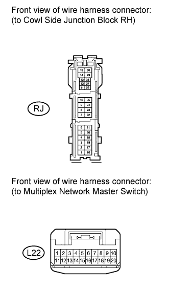
Disconnect the RJ connector.
-
Clear the DTC Click here.
-
Check for DTCs Click here.
OK DTCs B1214 and B1215 are not output.
NG
CHECK FOR DTC (MAIN BODY ECU LH (COWL SIDE JUNCTION BLOCK LH)) Click here
OK
REPAIR OR REPLACE HARNESS OR CONNECTOR (MAIN BODY ECU RH - MULTIPLEX NETWORK MASTER SWITCH)
-
-
CHECK FOR DTC (MAIN BODY ECU LH (COWL SIDE JUNCTION BLOCK LH))
-
Reconnect the L22 and RJ connectors.
-
Disconnect the Q3 and A30 connectors.
-
Clear the DTC Click here.
-
Check for DTCs Click here.
OK DTCs B1214 and B1215 are not output.
NG
CHECK HARNESS AND CONNECTOR (MAIN BODY ECU LH - FRONT CONTROLLER) Click here
OK
REPLACE MAIN BODY ECU LH (COWL SIDE JUNCTION BLOCK LH)
-
-
CHECK HARNESS AND CONNECTOR (MAIN BODY ECU LH - FRONT CONTROLLER)
-
Reconnect the Q3 connector.
-
Disconnect the 2F connector.
-
Turn the engine switch on (IG).
-
Clear the DTC Click here.
-
Check for DTCs Click here.
OK DTCs B1214 and B1215 are not output.
NG
CHECK HARNESS AND CONNECTOR (MAIN BODY ECU LH - CERTIFICATION ECU) Click here
OK
REPLACE HARNESS OR CONNECTOR (MAIN BODY ECU LH - FRONT CONTROLLER)
-
-
CHECK HARNESS AND CONNECTOR (MAIN BODY ECU LH - CERTIFICATION ECU)
-
Reconnect the 2F and A30 connectors.
-
Disconnect the P33 and Q3 connectors.
-
Measure the voltage and resistance according to the value(s) in the table below.
Standard Voltage Tester Connection Condition Specified condition P33-28 (MPX2) - Body ground Always Below 1 V Standard Resistance Tester Connection Condition Specified Condition P33-28 (MPX2) - Body ground Always 10 kΩ or higher
NG
REPAIR OR REPLACE HARNESS OR CONNECTOR (MAIN BODY ECU LH - CERTIFICATION ECU)
OK
-
-
CHECK HARNESS AND CONNECTOR (CERTIFICATION ECU (SMART KEY ECU ASSEMBLY) - EACH ECU)
-
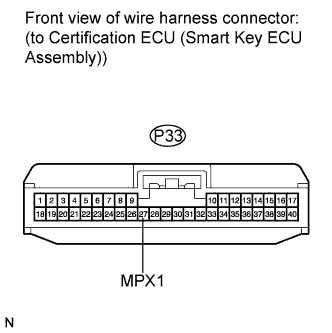
Disconnect the L22 connector.
-
Measure the voltage and resistance according to the value(s) in the table below.
Standard Voltage Tester Connection Condition Specified Condition P33-27 (MPX1) Body ground Always Below 1 V Standard Resistance Tester Connection Condition Specified condition P33-27 (MPX1) - Body ground Always 10 kΩ or higher
NG
REPAIR OR REPLACE HARNESS OR CONNECTOR (CERTIFICATION ECU (SMART KEY ECU ASSEMBLY) - EACH ECU)
OK
REPLACE CERTIFICATION ECU (SMART KEY ECU ASSEMBLY)
-