MULTIPLEX COMMUNICATION SYSTEM, Diagnostic DTC:B1209

| DTC Code | DTC Name |
|---|---|
| B1209 | Driver Side Outer Mirror |
DESCRIPTION
-
This DTC is detected if communication between the outer mirror control ECU (driver side outer mirror ECU) and gateway ECU stops for more than 10 seconds.
| DTC No. | DTC Detection Condition | Trouble Area |
|---|---|---|
| B1209 | Outer mirror control ECU (driver side) Communication stops |
|
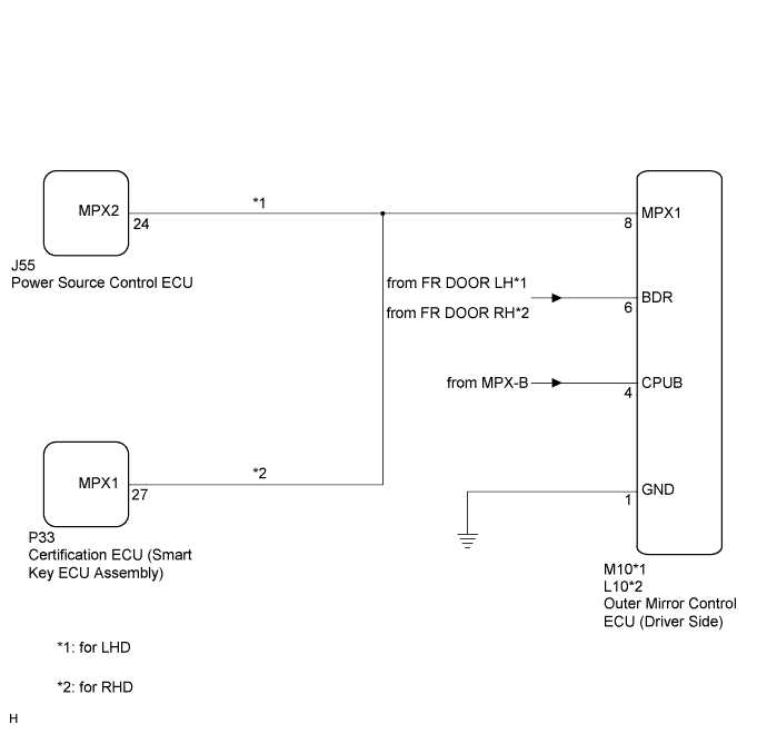
WIRING DIAGRAM
INSPECTION PROCEDURE
Tech Tips
If "+B of GND short malfunction of communication bus" DTCs (B1214 and B1215) are detected at the same time as "communication stop" DTC B1209, repair the "+B or GND short malfunction of communication bus" DTCs first Click here.
PROCEDURE
-
INSPECT FUSE (FR DOOR LH*1, FR DOOR RH*2, MPX-B)
-
Remove the FR DOOR LH fuse from the main body ECU LH (cowl side junction block LH)*1.
-
Remove the FR DOOR RH fuse from the main body ECU RH (cowl side junction block RH)*2.
-
Remove the MPX-B fuse from the engine room relay block No. 1.
-
Measure the resistance according to the value(s) in the table below.
Standard Resistance Tester Connection Condition Specified Condition FR DOOR LH fuse*1 Always Below 1 Ω FR DOOR RH fuse*2 Always Below 1 Ω MPX-B fuse Always Below 1 Ω
-
*1: for LHD
-
*2: for RHD
-
NG 
REPLACE FUSE
OK 
-
-
CHECK HARNESS AND CONNECTOR (OUTER MIRROR CONTROL ECU - BATTERY AND BODY GROUND)
-
Disconnect the M10 ECU connector*1.
-
Disconnect the L10 ECU connector*2.
-
Measure the voltage and resistance according to the value(s) in the table below.
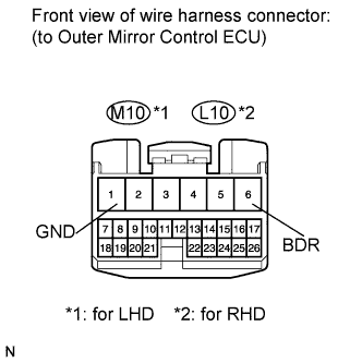
Standard Voltage Tester Connection Condition Specified Condition M10-6 (BDR)*1 - Body ground
L10-6 (BDR)*2 - Body ground
Always 11 to 14 V Standard Resistance Tester Connection Condition Specified Condition M10-1 (GND)*1 - Body ground
L10-1 (GND)*2 - Body ground
Always Below 1 Ω
-
*1: for LHD
-
*2: for RHD
-
NG
REPAIR OR REPLACE HARNESS OR CONNECTOR (OUTER MIRROR CONTROL ECU - BATTERY AND BODY GROUND)
OK
-
-
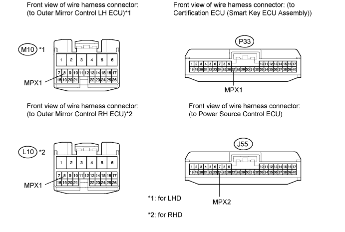
CHECK HARNESS AND CONNECTOR (COMMUNICATION LINE)
-
Disconnect the M10 and J55 ECU connectors*1.
-
Disconnect the L10 and P33 ECU connectors*2.
-
Measure the resistance according to the value(s) in the table below.
Standard Resistance Tester Connection Condition Specified Condition M10-8 (MPX1) - J55-24 (MPX2)*1
L10-8 (MPX1) - P33-27 (MPX1)*2
Always Below 1 Ω M10-8 (MPX1)*1 - Body ground
L10-8 (MPX1)*2 - Body ground
Always 10 kΩ or higher
-
*1: for LHD
-
*2: for RHD
-
NG
REPAIR OR REPLACE HARNESS OR CONNECTOR (COMMUNICATION LINE)
OK 
REPLACE OUTER MIRROR CONTROL ECU (DRIVER SIDE) Click here
-