MULTIPLEX COMMUNICATION SYSTEM, Diagnostic DTC:B1289

| DTC Code | DTC Name |
|---|---|
| B1289 | Passenger Seat ECU Communication Stop |
SYSTEM DESCRIPTION
This DTC is detected if communication between the front power seat switch (position control ECU) (passenger ECU) and gateway ECU stops for more than 10 seconds.
| DTC No. | DTC Detection Condition | Trouble Area |
|---|---|---|
| B1289 | Front power seat switch (position control ECU) (passenger seat) communication stops |
|
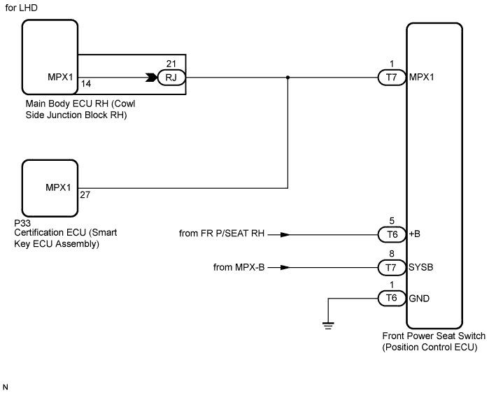
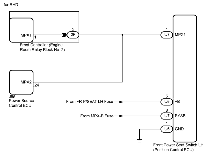
WIRING DIAGRAM
INSPECTION PROCEDURE
Tech Tips
If "+B of GND short malfunction of communication bus" DTCs (B1214 and B1215) are detected at the same time as "communication stop" DTC B1289, repair the "+B or GND short malfunction of communication bus" DTCs first Click here.
PROCEDURE
-
INSPECT FUSE (FR P/SEAT RH*1, FR P/SEAT LH*2, MPX-B)
-
Remove the FR P/SEAT RH fuse from the cowl side junction block RH*1.
-
Remove the FR P/SEAT LH fuse from the cowl side junction block LH*2.
-
Remove the MPX-B fuse from engine room relay block No. 1.
-
Measure the resistance according to the value(s) in the table below.
Standard Resistance Tester Connection Condition Specified Condition FR P/SEAT RH fuse*1 Always Below 1 Ω FR P/SEAT LH fuse*2 Always Below 1 Ω MPX-B fuse Always Below 1 Ω
-
*1: for LHD
-
*2: for RHD
-
NG 
REPLACE FUSE
OK 
-
-
CHECK HARNESS AND CONNECTOR (FRONT POWER SEAT SWITCH - BATTERY AND BODY GROUND)
-
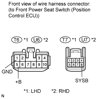
Disconnect the T6 and T7 ECU connectors*1.
-
Disconnect the U6 and U7 ECU connectors*2.
-
Measure the voltage and resistance according to the value(s) in the table below.
Standard Voltage Tester Connection Condition Specified Condition T6-5 (+B)*1 - Body ground
U6-5 (+B)*2 - Body ground
Always 11 to 14 V T7-8 (SYSB)*1 - Body ground
U7-8 (SYSB)*2 - Body ground
Always 11 to 14 V Standard Resistance Tester Connection Condition Specified Condition T6-1 (GND)*1 - Body ground
U6-1 (GND)*2 - Body ground
Always Below 1 Ω
-
*1: for LHD
-
*2: for RHD
-
NG
REPAIR OR REPLACE HARNESS OR CONNECTOR (FRONT POWER SEAT SWITCH - BATTERY AND BODY GROUND)
OK
-
-
CHECK HARNESS AND CONNECTOR
-
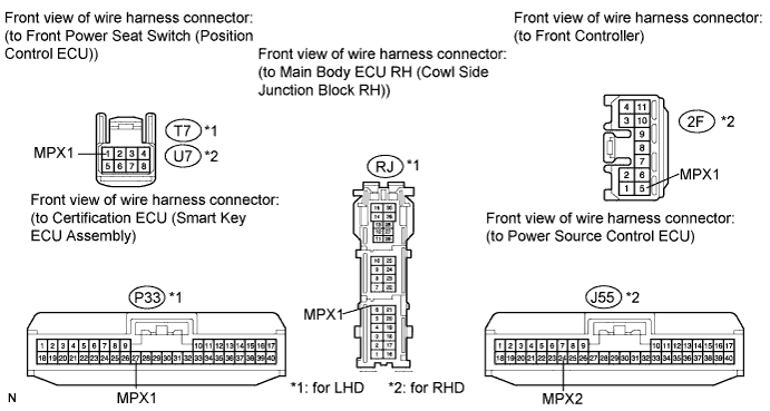
Disconnect the T7, RJ and P33 ECU connectors*1.
-
Disconnect the U7, 2F and J55 ECU connectors*2.
-
Measure the resistance according to the value(s) in the table below.
Standard Resistance Tester Connection Condition Specified Condition T7-1 (MPX1)*1 - RJ-21 (MPX1)
U7-1 (MPX1)*2 - 2F-5 (MPX1)
Always Below 1 Ω T7-1 (MPX1)*1 - P33-27 (MPX1)
U7-1 (MPX1)*2 - J55-24 (MPX2)
Always Below 1 Ω
-
*1: for LHD
-
*2: for RHD
-
NG
REPAIR OR REPLACE HARNESS OR CONNECTOR (COMMUNICATION LINE)
OK 
REPLACE FRONT POWER SEAT SWITCH (POSITION CONTROL ECU) Click here
-