MULTIPLEX COMMUNICATION SYSTEM TERMINALS OF ECU

-
CHECK GATEWAY ECU
-
Disconnect the gateway ECU connector.

-
Measure the voltage and resistance according to the value(s) in the table below.
Tester Connection Wiring Color Terminal Description Condition Specified Condition J76-1 (IG) - Body ground B - Body ground Power source (IG) Engine switch off Below 1 V J76-1 (IG) - Body ground B - Body ground Power source (IG) Engine switch on (IG) 11 to 14 V J76-2 (ACC) - Body ground O - Body ground Power source (ACC) Engine switch off Below 1 V J76-2 (ACC) - Body ground O - Body ground Power source (ACC) Engine switch: on (IG) 11 to 14 V J76-3 (MPD1) - Body ground GR - Body ground MPX line Always 10 kΩ or higher J76-4 (MPI1) - Body ground BR - Body ground MPX line Always 10 kΩ or higher J76-10 (BATT) - Body ground LG - Body ground Power source (+B) Always 11 to 14 V J76-12 (MPD2) - Body ground GR - Body ground MPX line Always 10 kΩ or higher J76-13 (MPI2) - Body ground BR - Body ground MPX line Always 10 kΩ or higher J76-24 (GND) - Body ground W-B - Body ground Ground for main power supply Always Below 1 Ω If the result is not as specified, there may be a malfunction on the wire harness side.
-
-
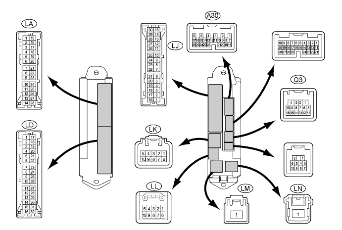
CHECK MAIN BODY ECU LH (COWL SIDE JUNCTION BLOCK LH)
-
Disconnect the main body ECU LH (cowl side junction block LH) connectors.
-
Measure the voltage and resistance according to the value(s) in the table below.
Tester Connection Wiring Color Terminal Description Condition Specified Condition A30-17 (MPX2) - Body ground GR - Body ground MPX line Always 10 kΩ or higher LD-3 (GND) - Body ground W-B - Body ground Ground for signal Always Below 1 Ω LD-8 (SGND) - Body ground W-B - Body ground Ground for signal Always Below 1 Ω LD-9 (SGND) - Body ground W-B - Body ground Ground for main power supply Always Below 1 Ω LD-18 (MPXB) - Body ground LG - Body ground Power source (+B) Always 11 to 14 V LJ-23 (BKUP) - Body ground Y - Body ground Power source (+B) Always 11 to 14 V Q3-15 (MPX1) - Body ground GR - Body ground MPX line Always 10 kΩ or higher If the result is not as specified, there may be a malfunction on the wire harness side.
-
-
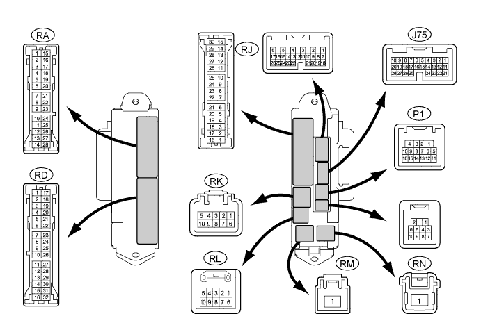
CHECK MAIN BODY ECU RH (COWL SIDE JUNCTION BLOCK RH)
-
Disconnect the main body ECU RH (cowl side junction block RH) connectors.
-
Measure the voltage and resistance according to the value(s) in the table below.
Tester Connection Wiring Color Terminal Description Condition Specified Condition J75-19 (MPX4) - Body ground GR - Body ground MPX line Always 10 kΩ or higher J75-20 (MPX6) - Body ground GR - Body ground MPX line Always 10 kΩ or higher J75-21 (MPX2) - Body ground GR - Body ground MPX line Always 10 kΩ or higher P1-5 (MPX5) - Body ground GR - Body ground MPX line Always 10 kΩ or higher RA-4 (GND2) - Body ground W-B - Body ground Ground for main power supply Always Below 1 Ω RA-5 (GND2) - Body ground W-B - Body ground Ground for main power supply Always Below 1 Ω RA-15 (ALTB) - Body ground SB - Body ground Power source (+B) Always 11 to 14 V RA-20 (MPX1) - Body ground GR - Body ground MPX line Always 10 kΩ or higher RD-7 (GND2) - Body ground W-B - Body ground Ground for main power supply Always Below 1 Ω RD-11 (GND2) - Body ground W-B - Body ground Ground for main power supply Always Below 1 Ω RD-17 (GND1) - Body ground W-B - Body ground Ground for main power supply Always Below 1 Ω RJ-21 (MPX1) - Body ground GR - Body ground MPX line Always 10 kΩ or higher RK-5 (BECU) - Body ground G-R - Body ground Power source (+B) Always 11 to 14 V RM-1 (IG) - Body ground B - Body ground Power source (IG) Engine switch off Below 1 V RM-1 (IG) - Body ground B - Body ground Power source (IG) Engine switch on (IG) 11 to 14 V RN-1 (BATB) - Body ground R - Body ground Power source (+B) Always 11 to 14 V
-
*1: for LHD
-
*2: for RHD
If the result is not as specified, there may be a malfunction on the wire harness side.
-
-
-
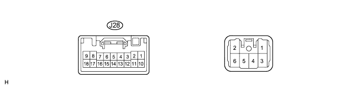
CHECK MULTIPLEX TILT AND TELESCOPIC ECU
-
Disconnect the multiplex tilt and telescopic ECU connector.
-
Measure the voltage and resistance according to the value(s) in the table below.
Tester Connection Wiring Color Terminal Description Condition Specified Condition J28-2 (+B) - Body ground SB - Body ground Power source (+B) Always 11 to 14 V J28-5 (MPX1) - Body ground GR - Body ground MPX line Always 10 kΩ or higher J28-8 (IG) - Body ground B - Body ground Power source (IG) Engine switch off Below 1 V J28-8 (IG) - Body ground B - Body ground Power source (IG) Engine switch on (IG) 11 to 14 V J28-9 (ECUB) - Body ground LG - Body ground Power source (+B) Always 11 to 14 V J28-11 (GND) - Body ground W-B - Body ground Ground for main power supply Always Below 1 Ω If the result is not as specified, there may be a malfunction on the wire harness side.
-
-
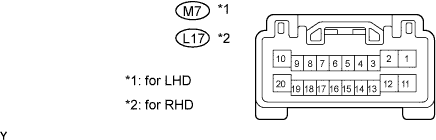
CHECK MULTIPLEX NETWORK MASTER SWITCH
-
Disconnect the multiplex network master switch connector.
-
Measure the voltage and the resistance according to the value(s) in the table below.
for LHD Tester Connection Wiring Color Terminal Description Condition Specified Condition M7-2 (GND) - Body ground W-B - Body ground Ground for main power supply Always Below 1 Ω M7-7 (MPX1) - Body ground GR - Body ground MPX line Always 10 kΩ or higher M7-8 (MPX2) - Body ground GR - Body ground MPX line Always 10 kΩ or higher M7-9 (CPUB) - Body ground G - Body ground Power source (+B) Always 11 to 14 V M7-10 (BDR) - Body ground L - Body ground Power source (+B) Always 11 to 14 V M7-20 (SIG) - Body ground B - Body ground Power source (IG) Engine switch off Below 1 V M7-20 (SIG) - Body ground B - Body ground Power source (IG) Engine switch on (IG) 11 to 14 V for RHD Tester Connection Wiring Color Terminal Description Condition Specified Condition L17-2 (GND) - Body ground W-B - Body ground Ground for main power supply Always Below 1 Ω L17-7 (MPX1) - Body ground GR - Body ground MPX line Always 10 kΩ or higher L17-8 (MPX2) - Body ground GR - Body ground MPX line Always 10 kΩ or higher L17-9 (CPUB) - Body ground G - Body ground Power source (+B) Always 11 to 14 V L17-10 (BDR) - Body ground L - Body ground Power source (+B) Always 11 to 14 V L17-20 (SIG) - Body ground B - Body ground Power source (IG) Engine switch off Below 1 V L17-20 (SIG) - Body ground B - Body ground Power source (IG) Engine switch on (IG) 11 to 14 V If the result is not as specified, there may be a malfunction on the wire harness side.
-
-
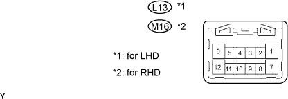
CHECK MULTIPLEX NETWORK SWITCH ASSEMBLY (for Front Passenger Side)
-
Disconnect the multiplex network switch connector.
-
Measure the voltage and resistance according to the value(s) in the table below.
for LHD Tester Connection Wiring Color Terminal Description Condition Specified Condition L13-2 (MPX1) - Body ground GR - Body ground MPX line Always 10 kΩ or higher L13-7 (GND) - Body ground W-B - Body ground Ground Always Below 1 Ω L13-12 (BDR) - L13-7 (GND) L - W-B +B power supply Always 11 to 14 V for RHD Tester Connection Wiring Color Terminal Description Condition Specified Condition M16-2 (MPX1) - Body ground GR - Body ground MPX line Always 10 kΩ or higher M16-7 (GND) - Body ground W-B - Body ground Ground Always Below 1 Ω M16-12 (BDR) - M16-7 (GND) L - W-B +B power supply Always 11 to 14 V If the result is not as specified, there may be a malfunction on the wire harness side.
-
-
CHECK MULTIPLEX NETWORK SWITCH ASSEMBLY (REAR LH)
-
Disconnect the multiplex network switch connector.

-
Measure the resistance according to the value(s) in the table below.
Tester Connection Wiring Color Terminal Description Condition Specified Condition O1-2 (MPX1) - Body ground W-B - Body ground MPX line Always 10 kΩ or higher O1-7 (GND) - Body ground W-B - Body ground Ground Always Below 1 O1-12 (BDR) - O1-7 (GND) O - W-B +B power supply Always 11 to 14 V If the result is not as specified, there may be a malfunction on the wire harness side.
-
-
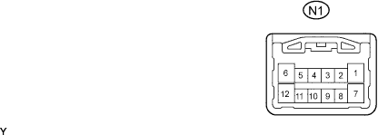
CHECK MULTIPLEX NETWORK SWITCH ASSEMBLY (REAR RH)
-
Disconnect the multiplex network switch connector.
-
Measure the voltage and resistance according to the value(s) in the table below.
Tester Connection Wiring Color Terminal Description Condition Specified Condition N1-2 (MPX1) - Body ground GR - body ground MPX line Always 10 kΩ or higher N1-7 (GND) - Body ground W-B - Body ground Ground Always Below 1 Ω N1-12 (BDR) - N1-7 (GND) O - W-B +B power supply Always 11 to 14 V If the result is not as specified, there may be a malfunction on the wire harness side.
-
-
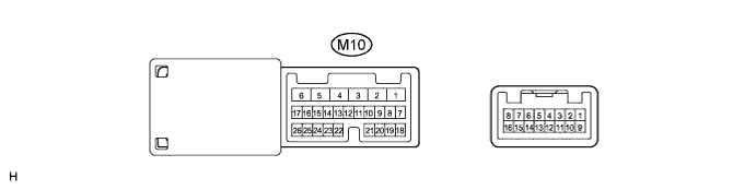
CHECK OUTER MIRROR CONTROL ECU LH
-
Disconnect the outer mirror control ECU LH connector.
-
Measure the voltage and resistance according to the value(s) in the table below.
Tester Connection Wiring Color Terminal Description Condition Specified Condition M10-1 (GND) - Body ground W-B - Body ground Ground for main power supply Always Below 1 Ω M10-3 (SIG) - Body ground B - Body ground Power source (IG) Engine switch off Below 1 V M10-3 (SIG) - Body ground B - Body ground Power source (IG) Engine switch on (IG) 11 to 14 V M10-4 (CPUB) - Body ground G - Body ground Power source (+B) Always 11 to 14 V M10-6 (BDR) - Body ground L - Body ground Power source (+B) Always 11 to 14 V M10-8 (MPX1) - Body ground GR - Body ground MPX line Always 10 kΩ or higher If the result is not as specified, there may be a malfunction on the wire harness side.
-
-
CHECK POWER SEAT CONTROL ECU RH
-
Disconnect the power seat control ECU RH connectors.

-
Measure the voltage and resistance according to the value(s) in the table below.
Tester Connection Wiring Color Terminal Description Condition Specified Condition T6-1 (GND) - Body ground W-B - Body ground Ground for main power supply Always Below 1 Ω T6-5 (+B) - Body ground L - Body ground Power source (+B) Always 11 to 14 V T7-1 (MPX1) - Body ground GR - Body ground MPX line Always 10 kΩ or higher T7-4 (IG) - Body ground B - Body ground Power source (IG) Engine switch off Below 1 V T7-4 (IG) - Body ground B - Body ground Power source (IG) Engine switch on (IG) 11 to 14 V T7-8 (SYSB) - Body ground P - Body ground Power source (+B) Always 11 to 14 V If the result is not as specified, there may be a malfunction on the wire harness side.
-
-
CHECK CERTIFICATION ECU (SMART KEY ECU ASSEMBLY)
-
Disconnect the certification ECU (smart key ECU assembly) connector.

-
Measure the voltage and resistance according to the value(s) in the table below.
Tester Connection Wiring Color Terminal Description Condition Specified Condition P33-1 (+B1) - Body ground L - Body ground Power source (+B) Always 11 to 14 V P33-17 (E) - Body ground W-B - Body ground Ground for main power supply Always Below 1 Ω P33-18 (IG) - Body ground B - Body ground Power source (IG) Engine switch off Below 1 V P33-18 (IG) - Body ground B - Body ground Power source (IG) Engine switch on (IG) 11 to 14 V P33-19 (ACC) - Body ground O - Body ground Power source (ACC) Engine switch off Below 1 V P33-19 (ACC) - Body ground O - Body ground Power source (ACC) Engine switch on (IG) 11 to 14 V P33-27 (MPX1) - Body ground GR - Body ground MPX line Always 10 kΩ or higher P33-28 (MPX2) - Body ground GR - Body ground MPX line Always 10 kΩ or higher If the result is not as specified, there may be a malfunction on the wire harness side.
-
-
CHECK FRONT CONTROLLER
-
Disconnect the front controller connectors.

-
Measure the voltage and resistance according to the value(s) in the table below.
Tester Connection Wiring Color Terminal Description Condition Specified Condition 2E-3 (FMIG) - Body ground B-Y - Body ground Power source (IG) Engine switch off Below 1 V 2E-3 (FMIG) - Body ground B-Y - Body ground Power source (IG) Engine switch on (IG) 11 to 14 V 2E-4 (FMB3) - Body ground G-R - Body ground Power source (+B) Always 11 to 14 V 2F-1 (E) - Body ground W-B - Body ground Ground for main power supply Always Below 1 Ω 2F-5 (MPX1) - Body ground L - Body ground MPX line Always 10 kΩ or higher 2F-6 (MPX2) - Body ground GR - Body ground MPX line Always 10 kΩ or higher If the result is not as specified, there may be a malfunction on the wire harness side.
-
-
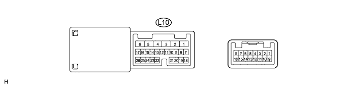
CHECK OUTER MIRROR CONTROL ECU RH
-
Disconnect the outer mirror control ECU RH connector.
-
Measure the voltage and the resistance according to the value(s) in the table below.
Tester Connection Wiring Color Terminal Description Condition Specified Condition L10-1 (GND) - Body ground W-B - Body ground Ground for main power supply Always Below 1 Ω L10-3 (SIG) - Body ground B - Body ground Power source (IG) Engine switch off Below 1 V L10-3 (SIG) - Body ground B - Body ground Power source (IG) Engine switch on (IG) 11 to 14 V L10-4 (CPUB) - Body ground G - Body ground Power source (+B) Always 11 to 14 V L10-6 (BDR) - Body ground L - Body ground Power source (+B) Always 11 to 14 V L10-8 (MPX1) - Body ground GR - Body ground MPX line Always 10 kΩ or higher If the result is not as specified, there may be a malfunction on the wire harness side.
-
-
CHECK FRONT POWER SEAT SWITCH LH (POSITION CONTROL ECU)
-
Disconnect the front power seat switch LH (position control ECU) connectors.

-
Measure the voltage and resistance according to the value(s) in the table below.
Tester Connection Wiring Color Terminal Description Condition Specified Condition U6-1 (GND) - Body ground W-B - Body ground Ground for main power supply Always Below 1 Ω U6-5 (+B) - Body ground L - Body ground Power source (+B) Always 11 to 14 V U7-1 (MPX1) - Body ground GR - Body ground MPX line Always 10 kΩ or higher U7-4 (IG) - Body ground Y - Body ground Power source (IG) Engine switch off Below 1 V U7-4 (IG) - Body ground Y - Body ground Power source (IG) Engine switch on (IG) 11 to 14 V U7-8 (SYSB) - Body ground LG - Body ground Power source (+B) Always 11 to 14 V If the result is not as specified, there may be a malfunction on the wire harness side.
-
-
CHECK SLIDING ROOF CONTROL ECU
-
Disconnect the sliding roof control ECU connector.

-
Measure the voltage and resistance according to the value(s) in the table below.
Tester Connection Wiring Color Terminal Description Condition Specified Condition R6-5 (B) - Body ground L - Body ground Power source (+B) Always 11 to 14 V R6-6 (IG) - Body ground V - Body ground Power source (IG) Engine switch off Below 1 V R6-6 (IG) - Body ground V - Body ground Power source (IG) Engine switch on (IG) 11 to 14 V R6-7 (E) - Body ground W-B - Body ground Ground for main power supply Always Below 1 Ω R6-10 (MPX1) - Body ground GR - Body ground MPX line Always 10 kΩ or higher If the result is not as specified, there may be a malfunction on the wire harness side.
-
-
CHECK RAIN SENSOR
-
Disconnect the rain sensor connector.

-
Measure the voltage and resistance according to the value(s) in the table below.
Tester Connection Wiring Color Terminal Description Condition Specified Condition R7-1 (SIG) - Body ground B - Body ground Power source (IG) Engine switch off Below 1 V R7-1 (SIG) - Body ground B - Body ground Power source (IG) Engine switch on (IG) 11 to 14 V R7-2 (MPX) - Body ground GR - Body ground MPX line Always 10 kΩ or higher If the result is not as specified, there may be a malfunction on the wire harness side.
-
-
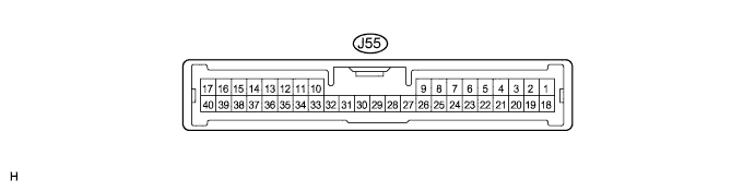
CHECK POWER SOURCE CONTROL ECU
-
Disconnect the power source control ECU connector.
-
Measure the voltage and resistance according to the value(s) in the table below.
Tester Connection Wiring Color Terminal Description Condition Specified Condition J55-6 (GND2) - Body ground W-B - Body ground Ground for main power supply Always Below 1 Ω J55-7 (MPX1) - Body ground GR - Body ground MPX line Always 10 kΩ or higher J55-12 (AM2) - Body ground O - Body ground Power source (+B) Always 11 to 14 V J55-24 (MPX2) - Body ground GR - Body ground MPX line Always 10 kΩ or higher J55-33 (AM1) - Body ground O - Body ground Power source (+B) Always 11 to 14 V If the result is not as specified, there may be a malfunction on the wire harness side.
-
-
CHECK WINDSHIELD WIPER SWITCH ASSEMBLY
-
Disconnect the windshield wiper switch assembly connector.

-
Measure the resistance and voltage according to the value(s) in the table below.
Tester Connection Wiring Color Terminal Description Condition Specified Condition J26-1 (B) - Body ground LG - Body ground Power source (+B) Always 11 to 14 V J26-2 (IG) - Body ground B - Body ground Power source (IG) Engine switch off Below 1 V J26-2 (IG) - Body ground B - Body ground Power source (IG) Engine switch on (IG) 11 to 14 V J26-5 (E) - Body ground W-B - Body ground Ground for main power supply Always Below 1 Ω J26-6 (MPX1) - Body ground GR - Body ground MPX line Always 10 kΩ or higher J26-7 (MPX2) - Body ground GR - Body ground MPX line Always 10 kΩ or higher If the result is not as specified, there may be a malfunction on the wire harness side.
-
-
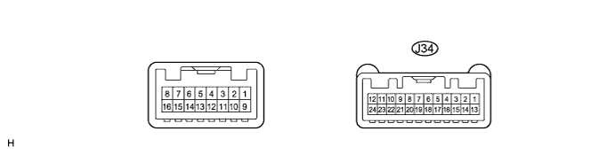
CHECK COMBINATION METER
-
Disconnect the combination meter connector.
-
Measure the voltage and resistance according to the value(s) in the table below.
Tester Connection Wiring Color Terminal Description Condition Specified Condition J34-1 (E2) - Body ground W-B - Body ground Ground for main power supply Always Below 1 Ω J34-6 (MPX+) - Body ground BR - Body ground MPX line Always 10 kΩ or higher J34-12 (IG+) - Body ground O - Body ground Power source (IG) Engine switch off Below 1 V J34-12 (IG+) - Body ground O - Body ground Power source (IG) Engine switch on (IG) 11 to 14 V J34-13 (ES) - Body ground W-B - Body ground Ground for main power supply Always Below 1 Ω J34-18 (MPX-) - Body ground BR - Body ground MPX line Always 10 kΩ or higher J34-23 (B) - Body ground L - Body ground Power source (+B) Always 11 to 14 V J34-24 (B) - Body ground LG - Body ground Power source (+B) Always 11 to 14 V If the result is not as specified, there may be a malfunction on the wire harness side.
-
-
CHECK CLEARANCE WARNING ECU
-
Disconnect the clearance warning ECU connector.

-
Measure the voltage and resistance according to the value(s) in the table below.
Tester Connection Wiring Color Terminal Description Condition Specified Condition Q37-8 (IG) - Body ground Y - Body ground Power source (IG) Engine switch off Below 1 V Q37-8 (IG) - Body ground Y - Body ground Power source (IG) Engine switch on (IG) 11 to 14 V Q37-26 (M+) - Body ground BR - Body ground MPX line Always 10 kΩ or higher Q37-27 (E) - Body ground W-B - Body ground Ground for main power supply Always Below 1 Ω If the result is not as specified, there may be a malfunction on the wire harness side.
-
-
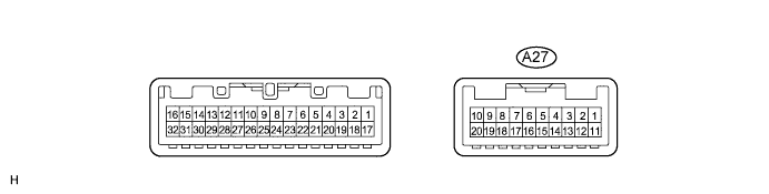
CHECK AFS ECU
-
Disconnect the AFS ECU connector.
-
Measure the voltage and resistance according to the value(s) in the table below.
Tester Connection Wiring Color Terminal Description Condition Specified Condition A27-1 (E1) - Body ground W-B - Body ground Ground for main power supply Always Below 1 Ω A27-2 (IG) - Body ground B-O - Body ground Power source (IG) Engine switch off Below 1 V A27-2 (IG) - Body ground B-O - Body ground Power source (IG) Engine switch on (IG) 11 to 14 V A27-5 (MPX1) - Body ground BR-R - Body ground MPX line Always 10 kΩ or higher A27-6 (MPX2) - Body ground BR - Body ground MPX line Always 10 kΩ or higher If the result is not as specified, there may be a malfunction on the wire harness side.
-
-
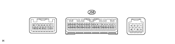
CHECK A/C AMPLIFIER
-
Disconnect the A/C amplifier connector.
-
Measure the voltage and the resistance according to the value(s) in the table below.
Tester Connection Wiring Color Terminal Description Condition Specified Condition J58-1 (B) - Body ground Y - Body ground Power source (+B) Always 11 to 14 V J58-20 (GND) - Body ground W-B - Body ground Ground for main power supply Always Below 1 Ω J58-21 (IG+) - Body ground B - Body ground Power source (IG) Engine switch off Below 1 V J58-21 (IG+) - Body ground B - Body ground Power source (IG) Engine switch on (IG) 11 to 14 V J58-30 (MPX+) - Body ground BR - Body ground MPX line Always 10 kΩ or higher J58-31 (MPX-) - Body ground BR - Body ground MPX line Always 10 kΩ or higher
-
-
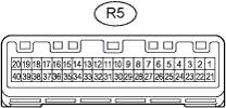
CHECK OVERHEAD JUNCTION BLOCK
-
Disconnect the overhead junction block connector.
-
Measure the resistance according to the value(s) in the table below.
Tester Connection Wiring Color Terminal Description Condition Specified Condition R5-1 (+B1) - Body ground L - Body ground Power source (IG) Always 11 to 14 V R5-18 (GND3) - Body ground W-B - Body ground Ground Always Below 1 Ω R5-36 (MPX) - Body ground GR - Body ground MPX line Always 10 kΩ or higher R5-37 (MPX1) - Body ground GR - Body ground MPX line Always 10 kΩ or higher R5-38 (MPX2) Body ground GR - Body ground MPX line Always 10 kΩ or higher R5-39 (GND) - Body ground W-B - Body ground Ground Always Below 1 Ω If the result is not as specified, there may be a malfunction on the wire harness side.
-
-
CHECK DOUBLE LOCK DOOR CONTROL RELAY
-
Measure the voltage and the resistance according to the value(s) in the table below.

Symbols (Terminal No.) Wiring Color Terminal Description Condition Specified Condition P34-1 (+B) - Body ground R - Body ground Power source (+B) Always 11 to 14 V P34-7 (CPUB) - Body ground LG - Body ground Power source (+B) Always 11 to 14 V P34-9 (MPX1) - Body ground GR - Body ground MPX line Always 10 kΩ or higher P34-14 (GND) - Body ground W-B - Body ground Ground for main power supply Always Below 1 Ω If the result is not as specified, there may be a malfunction on the wire harness side.
-