REAR VIEW MONITOR SYSTEM Reverse Signal Circuit
DESCRIPTION
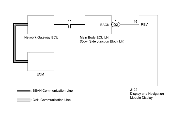
The display and navigation module display receives a reverse signal from the main body ECU LH (cowl side junction block LH) and information about the navigation antenna, and then adjusts the vehicle position on the navigation display. The ECM sends a reverse signal based on the shift position signal received from the park/neutral position switch assembly. The reverse signal sent from the ECM is received by the main body ECU LH (cowl side junction block LH) via the network gateway ECU using CAN communication and BEAN communication.
WIRING DIAGRAM
INSPECTION PROCEDURE
Note
Inspect the fuses for circuits related to this system before performing the following inspection procedure.
PROCEDURE
-
CHECK DISPLAY AND NAVIGATION MODULE DISPLAY
-
Disconnect the J122 connector from the display and navigation module display.
-
Measure the voltage according to the value(s) in the table below.
Standard Voltage Tester Connection Condition Specified Condition J122-16 (REV) - Body ground Engine switch on (IG)
Shift lever in R
11 to 14 V J122-16 (REV) - Body ground Engine switch on (IG)
Shift lever in any position except R
Below 1 V
NG 
CHECK HARNESS AND CONNECTOR (DISPLAY AND NAVIGATION MODULE DISPLAY - MAIN BODY ECU LH) Click here
OK 
PROCEED TO NEXT SUSPECTED AREA SHOWN IN PROBLEM SYMPTOMS TABLE Click here
-
-
CHECK HARNESS AND CONNECTOR (DISPLAY AND NAVIGATION MODULE DISPLAY - MAIN BODY ECU LH)
-
Disconnect the Q2 connector from the main body ECU LH (cowl side junction block LH).
-
Measure the resistance according to the value(s) in the table below.
Standard Resistance Tester Connection Condition Specified Condition J122-16 (REV) - Q2-2 (BACK) Always Below 1 Ω J122-16 (REV) - Body ground Always 10 kΩ or higher
NG 
REPAIR OR REPLACE HARNESS OR CONNECTOR
OK 
-
-
READ VALUE USING INTELLIGENT TESTER
-
Connect the intelligent tester to the DLC3.
-
Turn the engine switch on (IG).
-
Turn the intelligent tester on.
-
Enter the following menus: Powertrain / ECT / Data List.
-
According to the display on the intelligent tester, read the "Data List".
ECM Tester Display Test Part Control Range Diagnostic Note Shift SW Status (R Range) Park/neutral position switch status/
ON or OFF
Shift lever is:
-
ON: Shift lever is in R
-
OFF: Shift lever is not in R
When the shift lever position displayed on the intelligent tester differs from the actual position, the adjustment of the park/neutral position switch or shift cable may be incorrect OK Shift Lever Position Display R ON Except R OFF -
NG
GO TO AUTOMATIC TRANSMISSION SYSTEM (for AA80E) Click here
OK
-
-
REPLACE MAIN BODY ECU LH (COWL SIDE JUNCTION BLOCK LH)
-
Replace the main body ECU LH (cowl side junction block LH).
-
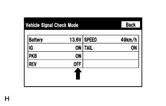
Enter "Vehicle Signal Check Mode".
Tech Tips
Refer to Check Vehicle Signal in Operation Check Click here.
-
Check that the display changes between ON and OFF according to the shift lever operation.
OK Shift Lever Position Display Except R OFF R ON Tech Tips
This display is updated once per second. As a result, it is normal for the display to lag behind the actual switch operation.
NG
REPLACE NETWORK GATEWAY ECU Click here
OK
END
-
-
REPLACE NETWORK GATEWAY ECU
-
Replace the network gateway ECU Click here.
-
Enter "Vehicle Signal Check Mode".
Tech Tips
Refer to Check Vehicle Signal in Operation Check Click here.
-
Check that the display changes between ON and OFF according to the shift lever operation.
OK Shift Lever Position Display Except R OFF R ON Tech Tips
This display is updated once per second. As a result, it is normal for the display to lag behind the actual switch operation.
NG
REPLACE ECM (for 2UR-GSE) Click here
OK
END
-