PARKING ASSIST MONITOR SYSTEM Display Signal Circuit between Television Camera ECU and Television Camera Assembly
DESCRIPTION
This is the display signal circuit of the television camera assembly.
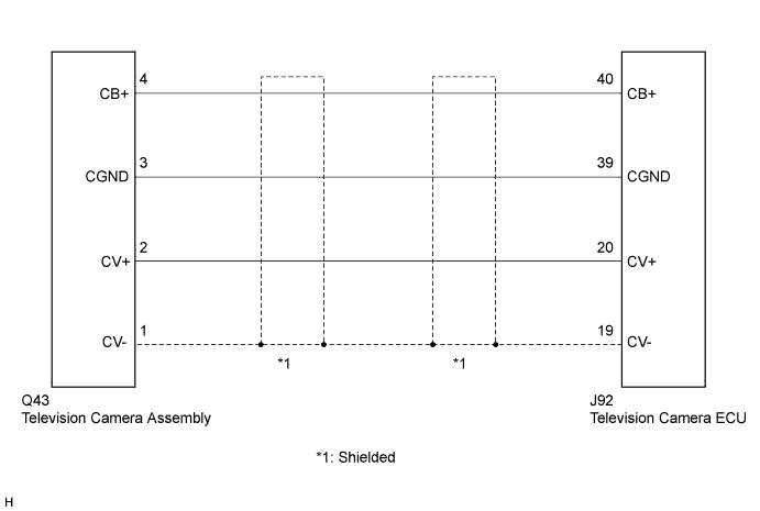
WIRING DIAGRAM
INSPECTION PROCEDURE
PROCEDURE
-
CHECK NAVIGATION DISPLAY
-
Check whether the navigation display appears properly or not.
OK The navigation display properly appears. Tech Tips
-
When the navigation display has trouble, inspect the circuit between the television camera ECU and multi-display Click here.
-
When the navigation display is normal, inspect the circuit between the television camera ECU and television camera assembly by following the steps below.
-
NG 
GO TO NAVIGATION SYSTEM Click here
OK 
-
-
CHECK HARNESS AND CONNECTOR (TELEVISION CAMERA ECU - TELEVISION CAMERA ASSEMBLY)
-
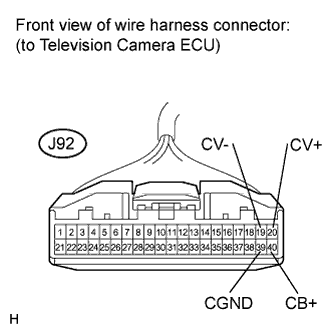
Disconnect the J92 connector from the television camera ECU.
-
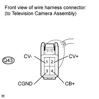
Disconnect the Q43 connector from the television camera assembly.
-
Measure the resistance according to the value(s) in the table below.
Standard Resistance Tester Connection Condition Specified Condition J92-40 (CB+) - Q43-4 (CB+) Always Below 1 Ω J92-39 (CGND) - Q43-3 (CGND) Always Below 1 Ω J92-20 (CV+) - Q43-2 (CV+) Always Below 1 Ω J92-19 (CV-) - Q43-1 (CV-) Always Below 1 Ω J92-40 (CB+) - Body ground Always 10 kΩ or higher J92-39 (CGND) - Body ground Always 10 kΩ or higher J92-20 (CV+) - Body ground Always 10 kΩ or higher J92-19 (CV-) - Body ground Always 10 kΩ or higher
NG
REPAIR OR REPLACE HARNESS OR CONNECTOR
OK
-
-
INSPECT TELEVISION CAMERA ECU
-
Reconnect the J92 connector to the television camera ECU.
-
Measure the voltage according to the value(s) in the table below.
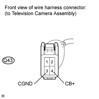
Standard Voltage Tester Connection Condition Specified Condition Q43-4 (CB+) - Q43-3 (CGND) Engine switch on (IG), shift lever in R 5.5 to 6.5 V
NG
REPLACE TELEVISION CAMERA ECU Click here
OK
-
-
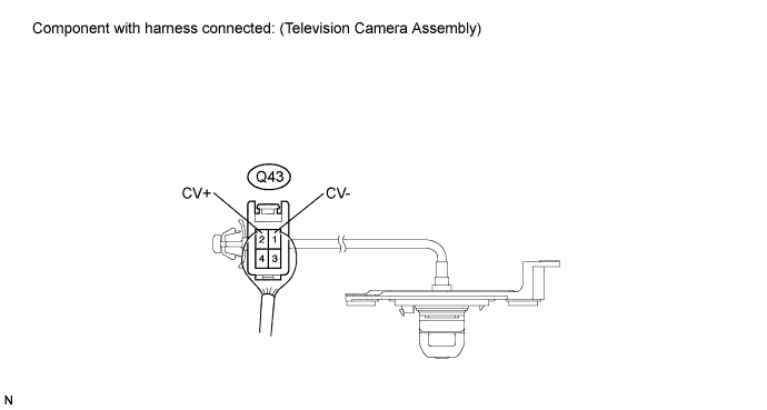
INSPECT TELEVISION CAMERA ASSEMBLY
-
Reconnect the Q43 connector to the television camera assembly.
-
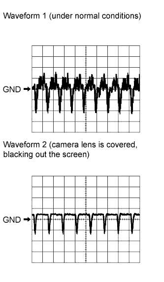
Check the waveform of the television camera assembly using an oscilloscope.
Item Content Measurement terminal Q43-2 (CV+) - Q43-1 (CV-) Measurement setting 0.2 V/DIV., 50 μsec./DIV. Condition Engine switch on (IG), shift lever in R OK Pulses are as shown in the illustration. Tech Tips
-
For waveform 1, the cycle is approximately 63.6 μsec and the waveform is almost entirely longitudinal.
-
For waveform 2, the cycle is approximately 63.6 μsec and the waveform is almost flat.
-
NG
REPLACE TELEVISION CAMERA ASSEMBLY Click here
OK 
PROCEED TO NEXT CIRCUIT INSPECTION SHOWN IN PROBLEM SYMPTOMS TABLE Click here
-