PARKING ASSIST MONITOR SYSTEM SYSTEM DESCRIPTION

-
GENERAL
-
This system has a television camera assembly mounted on the luggage compartment door to display the area behind the vehicle on the multi-display. The display panel also shows a composite view consisting of the area behind the vehicle and parking guidelines to assist the driver in parking the vehicle by monitoring the area behind the vehicle.
-
This system consists of the following components: television camera ECU, television camera assembly, multi-display, navigation ECU, park/neutral position switch, combination meter, and steering angle sensor.
-
This system is equipped with a self-diagnosis system, which is operated on a dedicated window that appears on the display panel, just as in the navigation system.
-
-
FUNCTION OF COMPONENTS
-
The television camera ECU controls the system by using information from the following components.
Item Function Television Camera Assembly
-
Mounted on the luggage compartment door to transmit the area behind the vehicle to the television camera ECU.
-
A color video camera that uses a CCD (Charge Coupled Device) and a wide- angle lens.
Television Camera ECU
-
Transmits video signals, which contain a composite of the rear view of the vehicle taken with the television camera and the parking assist guidelines, to the multi-display.
-
Effects overall control of the system by receiving signals from the sensors and the multi-display.
Multi-display Receives video signals containing a composite of the area behind the vehicle and the parking assist guideline signals from the television camera ECU, and displays them on the display panel. Navigation ECU Uses the yaw rate detected by the gyro sensor that is built into the navigation ECU to transmit the movement of the vehicle to the television camera ECU. Steering Angle Sensor Detects the angle of the steering wheel and sends the resulting signals to the television camera ECU through CAN communication. Combination Meter Transmits vehicle speed signals. Park/Neutral Position Switch Transmits a shift lever reverse position signal to the television camera ECU. Network Gateway ECU Converts signals from BEAN to CAN. -
-
-
OPERATION EXPLANATION
-
The reverse position signal is input from the park/neutral position switch to the television camera ECU when the shift lever is moved to R.
After receiving the reverse position signal, the television camera ECU switches the display signal for the multi-display from the navigation system to the parking assist monitor system.
-
In parallel parking assist mode, an appropriate steering angle and timing information can be provided for the driver when parallel parking. This is based on the information from the steering angle sensor signal and the vehicle angle data signal that are sent to the television camera ECU.
Tech Tips
-
In manual assist mode, the steering angle sensor signal and the vehicle angle data signal are not used to control parking assist.
-
The vehicle speed signal is required to adjust the steering angle neutral point.
-
-
-
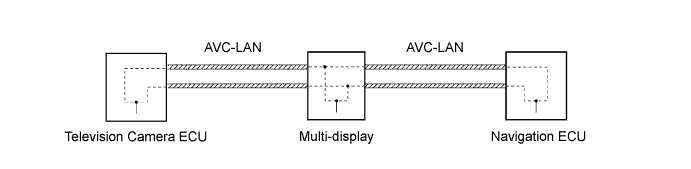
COMMUNICATION SYSTEM
-
This parking assist monitor system communicates between its components by AVC-LAN. Also, "PARALLEL PARKING ASSIST MODE" judges the vehicle angle data transmitted via AVC-LAN from the navigation ECU (the data is calculated by the navigation ECU by integrating the yaw rate of the gyro built in the navigation ECU).
-
-
DIAGNOSTIC FUNCTION
-
This parking assist monitor system has a diagnostic function.
-
A three-digit "unit code (physical address)" number (in hexadecimal notation) is set in each component that makes up the AVC-LAN.
-
A two-digit "logical address" number (in hexadecimal notation) is set in each function of the components that make up the AVC-LAN.
-
-
OUTLINE OF AVC-LAN
-
What is AVC-LAN?
AVC-LAN is the abbreviation for Audio Visual Communication-Local Area Network. This is a unified standard co-developed by 6 audio manufacturers associated with Toyota Motor Corporation.
The unified standard includes signals such as audio, visual, and signals for switch indication and communication.
-
Objectives
Recently, car audio systems have rapidly developed and the functions have vastly changed. The conventional system has been switched to a multi-media type such as a navigation system. At the same time, customers want to upgrade their audio systems. This is the factor that lies behind this standardization.
The objectives are explained as follows:
-
When products by different manufacturers were combined, malfunctions such as sound failure occurred. This kind of problem can be solved by standardizing signals.
-
Various types of after market products are available.
-
Because of the previously mentioned items, each manufacturer has been able to concentrate on developing products in their strongest field. This has enabled the development of inexpensive products.
-
In general, a new product developed by one particular manufacturer could not be used due to a lack of compatibility with other manufacturer's products. By developing this new standard, users can enjoy a range of compatible products from different manufacturers anytime they want.
Tech Tips
-
When a short to +B or short to GND is detected in the AVC-LAN circuit, communication stops, and the audio system does not function normally.
-
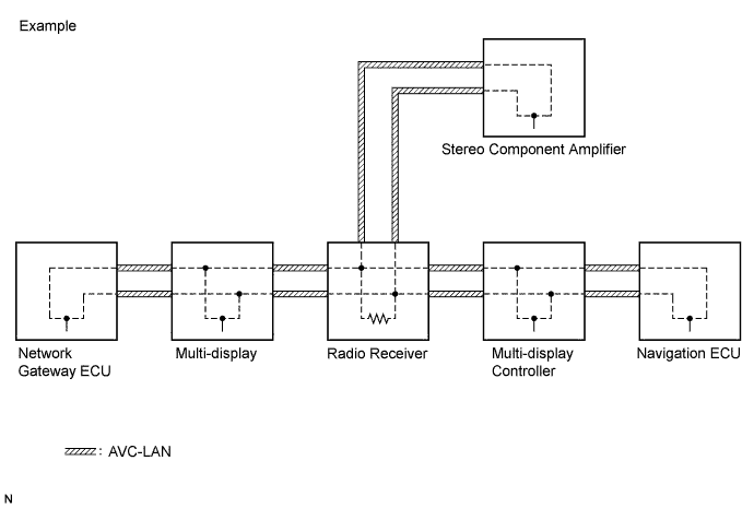
When the audio system is equipped with a navigation system, the multi-display is the master unit. When the audio system is not equipped with a navigation system, the radio receiver is the master unit.
-
The radio receiver is equipped with a resistor (60 to 80 Ω) for communication.
-
The car audio system using the AVC-LAN circuit has a diagnostic function.
-
Each product has its own specified number called a physical address (three-digit number). Numbers are also allotted to each function within a product, which are called logical addresses (two-digit number).
-
-
-
-
NOTES FOR PARKING ASSIST MONITOR
-
Notes for the parking assist monitor:
-
The parking assist monitor may not function properly if the television camera assembly is subjected to a severe blow by a hard object.
-
Do not scrub the cover part of the camera (resin made). Scrubbing it may scratch the cover and affect the image. Prevent organic solvents, waxes, bond removing solvents, or glass coating from adhering to the cover. Clean it off immediately, and wash with water.
-
Exposing the camera to sudden temperature changes may affect proper function.
-
A clear image may not appear if the camera is dirty with snow, mud, etc. In that case, wash with water and wipe to clean the lens. Use a detergent to remove dirt if necessary.
-
-
Images will be difficult to discern even in normal conditions if:
-
The display screen is frosted over (the image immediately after turning the engine switch on (IG) may be blurred or darker than normal).
-
A strong beam of light, such as a sunbeam or headlight, hits the camera.
-
It is too dark around the camera (at night, for example).
-
The ambient temperature around the camera is either too high or too low.
Tech Tips
When a strong light, such as a sunbeam reflected off a vehicle's body, hits the camera, the image may be blurred. This is called the "SMEAR" phenomenon, peculiar to the CCD camera.
-
-