AUDIO AND VISUAL SYSTEM (w/o Navigation System) USB Device or "iPod" cannot Charge
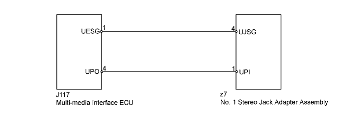
WIRING DIAGRAM
INSPECTION PROCEDURE
PROCEDURE
-
REPLACE USB DEVICE OR "iPod"
-
Disconnect the USB device or "iPod" from the No. 1 stereo jack adapter assembly.
-
Turn the engine switch off.
Tech Tips
When this malfunction occurs, it is necessary to turn off the engine switch to make it possible for the vehicle to recognize a new device when it is connected.
-
Turn the engine switch on (ACC).
-
Connect a known good USB device or "iPod" to the No. 1 stereo jack adapter assembly.
OK USB device or "iPod" charges.
NG 
INSPECT MULTI-MEDIA INTERFACE ECU Click here
OK 
USB DEVICE OR "iPod" WAS DEFECTIVE
-
-
INSPECT MULTI-MEDIA INTERFACE ECU
-
Disconnect the No. 1 stereo jack adapter assembly connector.
-
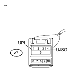
Text in Illustration *1 Front view of wire harness connector
(to No. 1 Stereo Jack Adapter Assembly)
Measure the voltage according to the value(s) in the table below.
Standard Voltage Tester Connection Condition Specified Condition z7-1 (UPI) - z7-4 (UJSG) Always 5 V
NG
CHECK HARNESS AND CONNECTOR Click here
OK
REPLACE NO. 1 STEREO JACK ADAPTER ASSEMBLY Click here
-
-
CHECK HARNESS AND CONNECTOR
-
Disconnect the multi-media interface ECU connector.
-
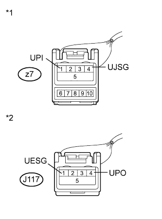
Text in Illustration *1 Front view of wire harness connector
(to No. 1 Stereo Jack Adapter Assembly)
*2 Front view of wire harness connector
(to Multi-media Interface ECU)
Measure the resistance according to the value(s) in the table below.
Standard Resistance Tester Connection Condition Specified Condition J117-4 (UPO) - z7-1 (UPI) Always Below 1 Ω J117-1 (UESG) - z7-4 (UJSG) Always Below 1 Ω z7-1 (UPI) - Body ground Always 10 kΩ or higher z7-4 (UJSG) - Body ground Always 10 kΩ or higher
NG 
REPAIR OR REPLACE HARNESS OR CONNECTOR
OK
PROCEED TO NEXT SUSPECTED AREA SHOWN IN PROBLEM SYMPTOMS TABLE Click here
-