AUDIO AND VISUAL SYSTEM Stereo Component Amplifier Power Source Circuit
DESCRIPTION
This circuit provides power to the stereo component amplifier.
WIRING DIAGRAM
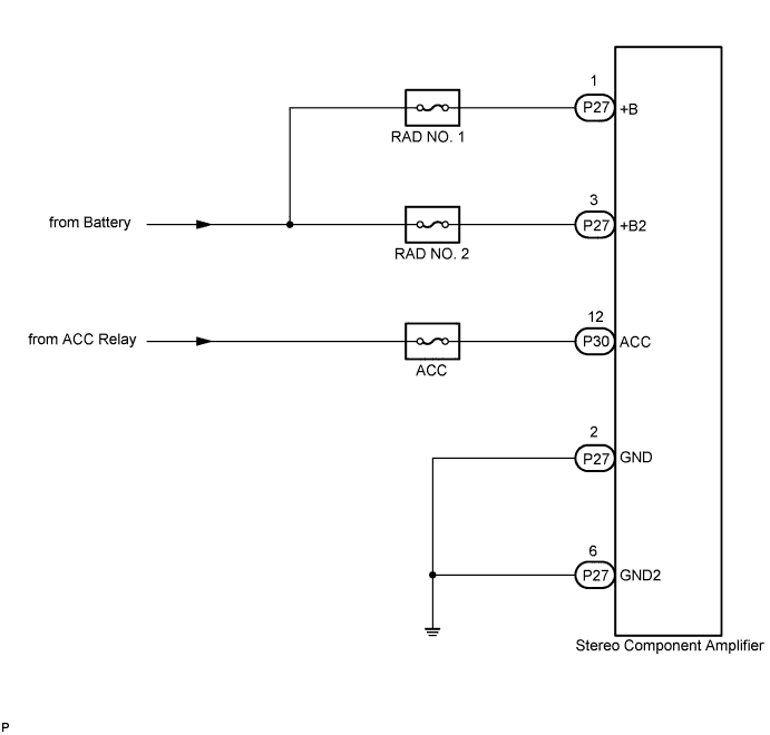
INSPECTION PROCEDURE
PROCEDURE
-
INSPECT STEREO COMPONENT AMPLIFIER
-
Disconnect the stereo component amplifier connectors.
-
Measure the resistance according to the value(s) in the table below.
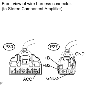
Standard Resistance Tester Connection Condition Specified Condition P27-2 (GND) - Body ground Always Below 1 Ω P27-6 (GND2) - Body ground Always Below 1 Ω -
Measure the voltage according to the value(s) in the table below.
Standard Voltage Tester Connection Condition Specified Condition P27-1 (+B) - P27-2 (GND) Always 11 to 14 V P27-3 (+B2) - P27-2 (GND) Always 11 to 14 V P30-12 (ACC) - P27-2 (GND) Engine switch on (ACC) 11 to 14 V
NG 
REPAIR OR REPLACE HARNESS OR CONNECTOR
OK 
PROCEED TO NEXT CIRCUIT INSPECTION SHOWN IN PROBLEM SYMPTOMS TABLE Click here
-