AUDIO AND VISUAL SYSTEM Radio Receiver Power Source Circuit
DESCRIPTION
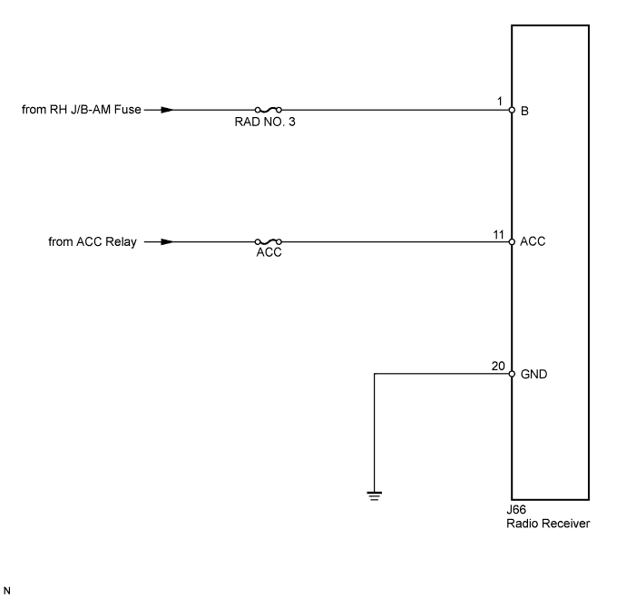
This circuit provides power to the radio receiver.
WIRING DIAGRAM
INSPECTION PROCEDURE
PROCEDURE
-
INSPECT RADIO RECEIVER
-
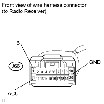
Disconnect the radio receiver connector.
-
Measure the resistance according to the value in the table below.
Standard Resistance Tester Connection Condition Specified Condition J66-20 (GND) - Body ground Always Below 1 Ω -
Measure the voltage according to the values in the table below.
Standard Voltage Tester Connection Condition Specified Condition J66-1 (B) - J66-20 (GND) Always 11 to 14 V J66-11 (ACC) - J66-20 (GND) Engine switch on (ACC) 11 to 14 V
NG 
REPAIR OR REPLACE HARNESS OR CONNECTOR
OK 
PROCEED TO NEXT CIRCUIT INSPECTION SHOWN IN PROBLEM SYMPTOMS TABLE Click here
-