STEERING LOCK SYSTEM Power Source Circuit
DESCRIPTION
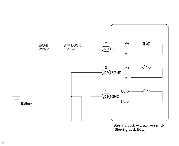
This circuit supplies power source voltage from the battery to terminal B of the steering lock ECU. This is used as power source for the CPU, motor, communication, and peripheral circuits.
WIRING DIAGRAM
INSPECTION PROCEDURE
PROCEDURE
-
CHECK HARNESS AND CONNECTOR (STEERING LOCK ACTUATOR ASSEMBLY - BODY GROUND)
-
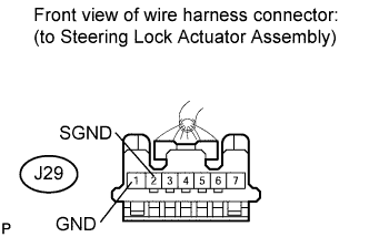
Disconnect the J29 connector from the steering lock actuator assembly.
-
Measure the resistance according to the value(s) in the table below.
Standard Resistance Tester Connection Condition Specified Condition J29-1 (GND) - Body ground Always Below 1 Ω J29-2 (SGND) - Body ground Always Below 1 Ω
NG 
REPAIR OR REPLACE HARNESS OR CONNECTOR
OK 
-
-
CHECK HARNESS AND CONNECTOR (STEERING LOCK ACTUATOR ASSEMBLY - BATTERY)
-
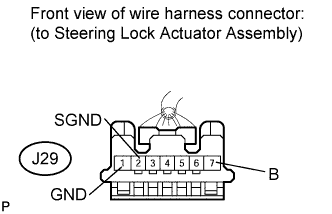
Measure the voltage according to the value(s) in the table below.
Standard Voltage Tester Connection Condition Specified Condition J29-7 (B) - J29-1 (GND) Always 10 to 14 V J29-7 (B) - J29-2 (SGND) Always 10 to 14 V
NG
REPAIR OR REPLACE HARNESS OR CONNECTOR (STEERING LOCK ACTUATOR ASSEMBLY - BATTERY)
OK 
PROCEED TO NEXT CIRCUIT INSPECTION SHOWN IN PROBLEM SYMPTOMS TABLE Click here
-