STEERING COLUMN ASSEMBLY REMOVAL

CAUTION:
Some of these service operations affect the SRS airbag system. Read the precautionary notices concerning the SRS airbag system before servicing Click here.
-
PRECAUTION
-
ALIGN FRONT WHEELS FACING STRAIGHT AHEAD
-
DISCONNECT CABLE FROM NEGATIVE BATTERY TERMINAL
-
Disable the auto tilt away function by changing the customize parameter Click here.
Note
Record the current customize parameter setting (whether the auto tilt away function is enabled or disabled) in order to restore the current setting after finishing this operation.
Tech Tips
Performing the above operation disables the auto tilt away function when the engine switch is turned off.
-
Turn the engine switch on (IG). Operate the tilt and telescopic switch to fully extend and lower the steering column assembly.
-
Turn the engine switch off and disconnect the cable from the negative (-) battery terminal.
CAUTION:
Wait at least 90 seconds after disconnecting the cable from the negative (-) battery terminal to disable the SRS system.
Note
When disconnecting the cable, some systems need to be initialized after the cable is reconnected Click here.
-
-
REMOVE LOWER NO. 3 STEERING WHEEL COVER
-
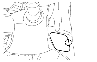
Disengage the claw and remove the lower No. 3 steering wheel cover.
-
-
REMOVE LOWER NO. 2 STEERING WHEEL COVER
-
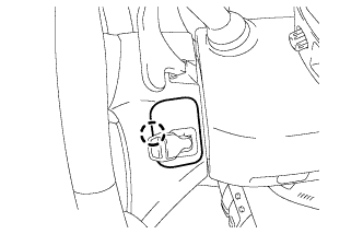
Disengage the claw and remove the lower No. 2 steering wheel cover.
-
-
REMOVE STEERING PAD
-
Check that the engine switch is off.
-
Check that the cable is disconnected from the negative (-) battery terminal.
CAUTION:
Wait at least 90 seconds after disconnecting the cable from the negative (-) battery terminal to disable the SRS system.
-
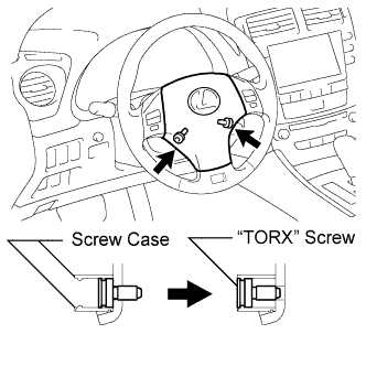
Using a T30 "TORX" socket wrench, loosen the 2 "TORX" screws until the groove along the screw circumference catches on the screw case.
-
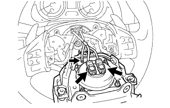
Pull out the steering pad from the steering wheel assembly.
Note
When removing the steering pad, do not pull the airbag wire harness.
-
Disconnect the horn connector from the steering pad.
-
Disconnect the 2 airbag connectors and remove the steering pad.
Note
When disconnecting the airbag connector, take care not to damage the airbag wire harness.
-
-
REMOVE STEERING WHEEL ASSEMBLY
-
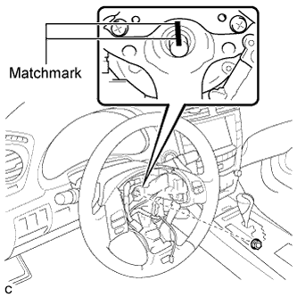
Remove the steering wheel assembly set nut.
-
Put matchmarks on the steering wheel assembly and the steering main shaft.
-
Disconnect the connectors from the spiral cable.
-

Install SST to the steering wheel assembly as shown in the illustration.
- SST
- 09950-50013 ( 09951-05010, 09952-05010, 09953-05020, 09954-05021 )
Note
Apply a small amount of grease to the threads and tip of SST (09953-05020) before use.
-
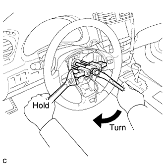
Using SST, remove the steering wheel assembly.
-
-
REMOVE STEERING COLUMN COVER
-
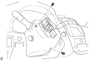
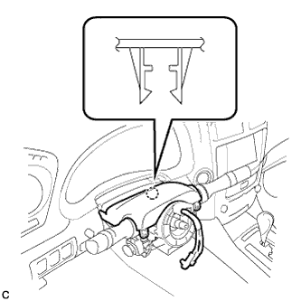
Remove the 3 screws.
-
Disengage the 2 claws to remove the lower steering column cover.
Note
Do not damage the tilt and telescopic switch.
-
Disengage the claw.
-
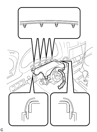
Disengage the 4 clips and 2 guides to separate the upper steering column cover.
-
-
REMOVE TILT AND TELESCOPIC SWITCH
-
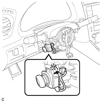
Disconnect the connector.
-
Disengage the claw and pull out the tilt and telescopic switch.
Note
Pushing on the claw too hard will break the claw.
-
-
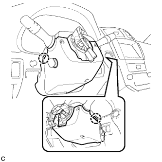
REMOVE TURN SIGNAL SWITCH ASSEMBLY WITH SPIRAL CABLE SUB-ASSEMBLY
-
Disconnect the connectors from the turn signal switch assembly with spiral cable sub-assembly.
-
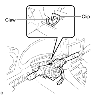
Using pliers, grip the claws of the clip and remove the turn signal switch assembly with spiral cable sub-assembly from the steering column assembly.
-
-
REMOVE DRIVER SIDE KNEE AIRBAG ASSEMBLY
Tech Tips
Refer to the instructions for Removal of the driver side knee airbag assembly Click here.
-
REMOVE NO. 1 AIR DUCT
-
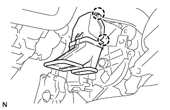
Disengage the 2 claws and remove the No. 1 air duct.
-
-
REMOVE BRAKE PEDAL RETURN SPRING
-
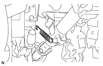
Remove the brake pedal return spring.
-
-
SEPARATE STEERING SLIDING YOKE SUB-ASSEMBLY
-
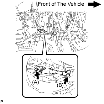
Loosen the bolt (A) and remove the bolt (B), then slide the steering sliding yoke sub-assembly.
Note
-
Do not remove the bolt (A).
-
Do not separate the steering sliding yoke sub-assembly from the power steering gear assembly.
-
-
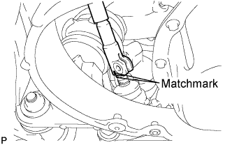
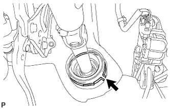
Put matchmarks on the steering sliding yoke sub-assembly and the power steering link assembly.
-
Separate the steering sliding yoke sub-assembly from the power steering link assembly.
-
-
REMOVE STEERING COLUMN ASSEMBLY
-
Remove the clamp from the steering column hole shield.
-
Disconnect the connectors and wire harness clamps from the steering column assembly.
-
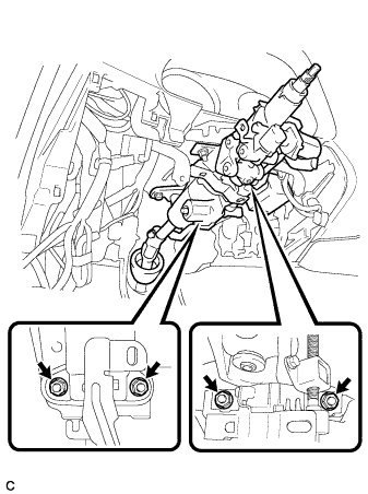
Remove the 4 nuts and steering column assembly.
-
-
REMOVE STEERING SLIDING YOKE SUB-ASSEMBLY
-
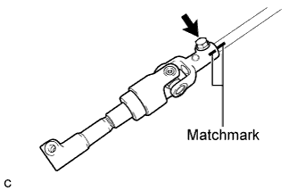
Put matchmarks on the steering sliding yoke sub-assembly and the No. 2 steering intermediate shaft assembly.
-
Remove the bolt and steering sliding yoke sub-assembly from the No. 2 steering intermediate shaft assembly.
-
-
REMOVE NO. 2 STEERING INTERMEDIATE SHAFT ASSEMBLY
-
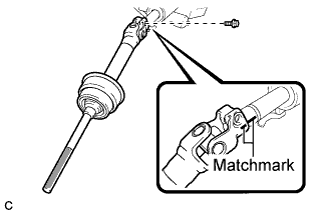
Put matchmarks on the No. 2 steering intermediate shaft assembly and the steering column assembly.
-
Remove the bolt and the No. 2 steering intermediate shaft assembly from the steering column assembly.
-