POWER TILT AND POWER TELESCOPIC STEERING COLUMN SYSTEM Actuator Power Source Circuit
DESCRIPTION
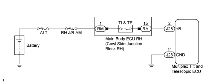
This is the power source for the motors.
WIRING DIAGRAM
INSPECTION PROCEDURE
PROCEDURE
-
INSPECT FUSE (TI & TE)
-
Remove the TI & TE fuse from the main body ECU RH (cowl side junction block RH).
-
Measure the resistance according to the value(s) to the table below.
Standard Resistance Tester Connection Condition Specified Condition TI & TE fuse Always Below 1 Ω
NG 
REPLACE FUSE
OK 
-
-
CHECK HARNESS AND CONNECTOR (MULTIPLEX TILT AND TELESCOPIC ECU - BATTERY)
-
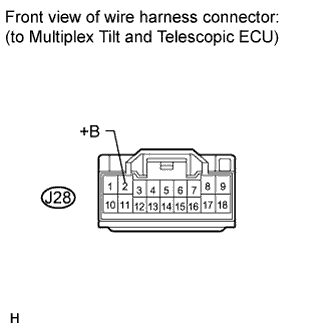
Disconnect the J28 connector from the multiplex tilt and telescopic ECU.
-
Measure the voltage according to the value(s) in the table below.
Standard Voltage Tester Connection Condition Specified Condition J28-2 (+B) - Body ground Always 11 to 14 V
NG 
CHECK HARNESS AND CONNECTOR (MULTIPLEX TILT AND TELESCOPIC ECU - MAIN BODY ECU RH) Click here
OK
-
-
CHECK HARNESS AND CONNECTOR (MULTIPLEX TILT AND TELESCOPIC ECU - BODY GROUND)
-
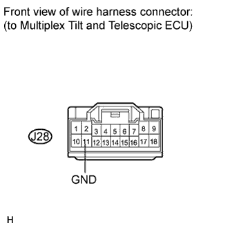
Measure the resistance according to the value(s) in the table below.
Standard Resistance Tester Connection Condition Specified Condition J28-11 (GND) - Body ground Always Below 1 Ω
NG
REPAIR OR REPLACE HARNESS OR CONNECTOR
OK 
PROCEED TO NEXT CIRCUIT INSPECTION SHOWN IN PROBLEM SYMPTOMS TABLE Click here
-
-
CHECK HARNESS AND CONNECTOR (MULTIPLEX TILT AND TELESCOPIC ECU - MAIN BODY ECU RH)
-
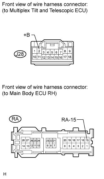
Disconnect the RA connector from the main body ECU RH (cowl side junction block RH).
-
Measure the resistance according to the value(s) in the table below.
Standard Resistance Tester Condition Condition Specified Condition J28-2 (+B) - RA-15 Always Below 1 Ω J28-2 (+B) - Body ground Always 10 kΩ or higher
NG
REPAIR OR REPLACE HARNESS OR CONNECTOR (MULTIPLEX TILT AND TELESCOPIC ECU - MAIN BODY ECU RH)
OK
REPAIR OR REPLACE HARNESS OR CONNECTOR (BATTERY - MAIN BODY ECU RH (COWL SIDE JUNCTION BLOCK RH))
-