POWER STEERING SYSTEM, Diagnostic DTC:C1552, C1554

| DTC Code | DTC Name |
|---|---|
| C1552 | PIG Power Supply Voltage Malfunction |
| C1554 | Power Supply Relay Failure |
DESCRIPTION
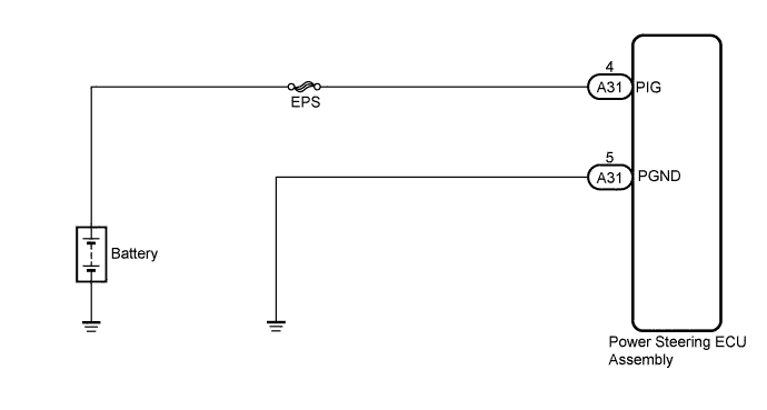
This circuit supplies power to drive the power steering motor.
| DTC No. | DTC Detection Condition | Trouble Area |
|---|---|---|
| C1552 | This DTC is detected when power source voltage drops or remains high. |
|
| C1554 | Power source relay malfunction is detected. |
WIRING DIAGRAM
INSPECTION PROCEDURE
PROCEDURE
-
CHECK CONNECTORS
-
Check the connection of the power steering ECU connector.
-
Visually inspect the terminals of the power steering ECU connector.
Result Result Proceed to Normal A Connectors not properly connected B Power steering ECU connector terminals abnormal C Note
If replacing the power steering ECU assembly, initialize the rotation angle sensor value and calibrate the torque sensor zero point Click here.
B 
CONNECT CONNECTORS CORRECTLY
C
REPLACE POWER STEERING ECU ASSEMBLY Click here
A 
-
-
INSPECT FUSE (EPS FUSE)
-
Remove the EPS fuse from the engine room No. 1 relay block.
-
Measure the resistance according to the value(s) in the table below.
Standard Resistance Tester Connection Condition Specified Condition EPS fuse Always Below 1 Ω
NG
REPLACE FUSE
OK
-
-
CHECK HARNESS AND CONNECTOR (POWER STEERING ECU ASSEMBLY - BATTERY)
-
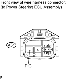
Disconnect the A31 connector from the power steering ECU assembly.
-
Measure the voltage according to the value(s) in the table below.
Standard Voltage Tester Connection Condition Specified Condition A31-4 (PIG) - Body ground Always 11 to 14 V
NG
REPAIR OR REPLACE HARNESS OR CONNECTOR
OK
-
-
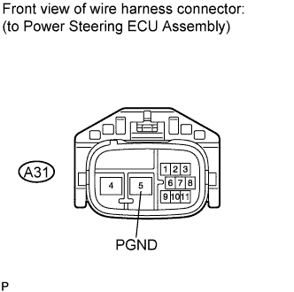
CHECK HARNESS AND CONNECTOR (POWER STEERING ECU ASSEMBLY - BODY GROUND)
-
Measure the resistance according to the value(s) in the table below.
Standard Resistance Tester Connection Condition Specified Condition A31-5 (PGND) - Body ground Always Below 1 Ω Note
If replacing the power steering ECU assembly, initialize the rotation angle sensor value and calibrate the torque sensor zero point Click here.
NG
REPAIR OR REPLACE HARNESS OR CONNECTOR
OK 
REPLACE POWER STEERING ECU ASSEMBLY Click here
-