POWER STEERING SYSTEM, Diagnostic DTC:C1551

| DTC Code | DTC Name |
|---|---|
| C1551 | IG Power Supply Voltage Malfunction |
DESCRIPTION
If the power steering ECU assembly determines that there is a malfunction in the IG power source circuit, it outputs this DTC. This DTC is not output when there is an open circuit in the wire harness connected to terminal IG or a battery voltage drop.
| DTC No. | DTC Detection Condition | Trouble Area |
|---|---|---|
| C1551 | IG power source circuit malfunction | Power steering ECU assembly |
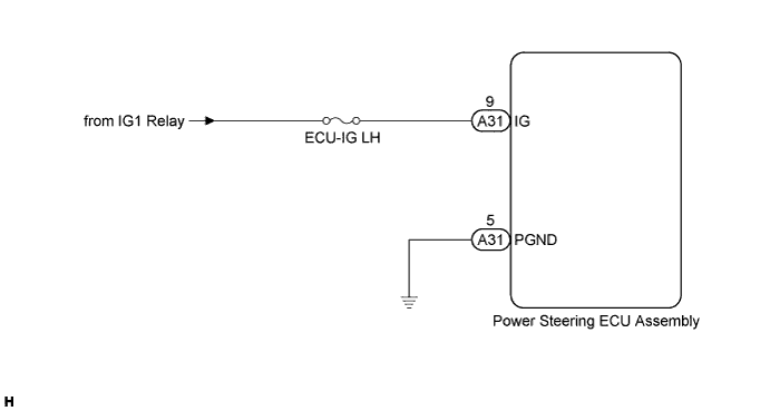
WIRING DIAGRAM
INSPECTION PROCEDURE
PROCEDURE
-
INSPECT FUSE (ECU-IG LH)
-
Remove the ECU-IG LH fuse from the cowl side junction block LH.
-
Measure the resistance according to the value(s) in the table below.
Standard Resistance Tester Connection Condition Specified Condition ECU-IG LH fuse Always Below 1 Ω
NG 
REPLACE FUSE
OK 
-
-
CHECK HARNESS AND CONNECTOR (POWER STEERING ECU ASSEMBLY - BATTERY)
-
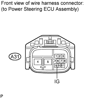
Disconnect the A31 connector from the power steering ECU assembly.
-
Measure the voltage according to the value(s) in the table below.
Standard Voltage Tester Connection Switch Condition Specified Condition A31-9 (IG) - Body ground Engine switch on (IG) 11 to 14 V
NG
REPAIR OR REPLACE HARNESS OR CONNECTOR
OK
-
-
CHECK HARNESS AND CONNECTOR (POWER STEERING ECU ASSEMBLY - BODY GROUND)
-
Measure the resistance according to the value(s) in the table below.
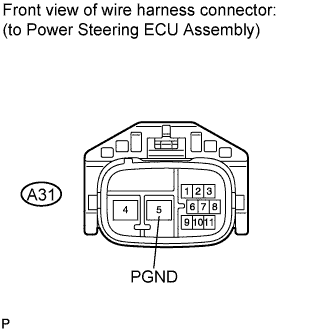
Standard Resistance Tester Connection Condition Specified Condition A31-5 (PGND) - Body ground Always Below 1 Ω Note
Replace the power steering ECU assembly, initialize the rotation angle sensor value and calibrate the torque sensor zero point Click here.
NG
REPAIR OR REPLACE HARNESS OR CONNECTOR
OK 
REPLACE POWER STEERING ECU ASSEMBLY Click here
-